Pin8
(ERR+)
Pin18
(‐COM)
Pin6
(STOP+)
Pin18
(‐COM)
Pin12
(LOAD+)
Pin13
(LOAD−)
(3)ERR(TripSignalOutput)(CN2:Pin8,Pin18)
PhotoCouplerisolatedTransistorOutput.
(Max.RatingofTransistorisVCEO=50V,
Ic=50mA,Pc=100mW)Pleaseuseatlessthanthe
maximumrating
ForASTRO-E400/500(NE52),thetripsignaltransistoris
ONwhenatripsignalisoutput.TheErrorOutputCode
fromNE147-400NE147,NE147-800needstobereversed
tomaintainthecompatibilitywithNE52,usethefollowing
process.
①TurnthePowerSwitchOFF
②Removethetopcoverfromthecontrolunit.
③TurnoffNo.1dipswitch.DONOTchangeanyotherdip
switches.
④Reinstallthetopcover.
(4)LOAD(LoadSignal)(CN2:Pin12,Pin13)
DCVoltageisoutput:+0〜15VDCinproportiontoMotor
Load.
(5)STOP(RotationStop)(CN2:Pin6,Pin18)
PhotoCouplerisolatedTransistorOutput
WhenMotorisstopped,TransistorisOFF.
TheMax.RatingofTransistorisVCEO=50V,Ic=50mA,
Pc=100mW.
Pleaseuseatlessthanthemaximumrating.
Atfactoryshipment
Incasetheerroroutputtheoryisreversed
12345678910
12345678910
h
ON
ON
! " #
!
$%&'()*
' )*+) ,# , -!. /
, 0# )*+) #, ,#
!
$%&'()*
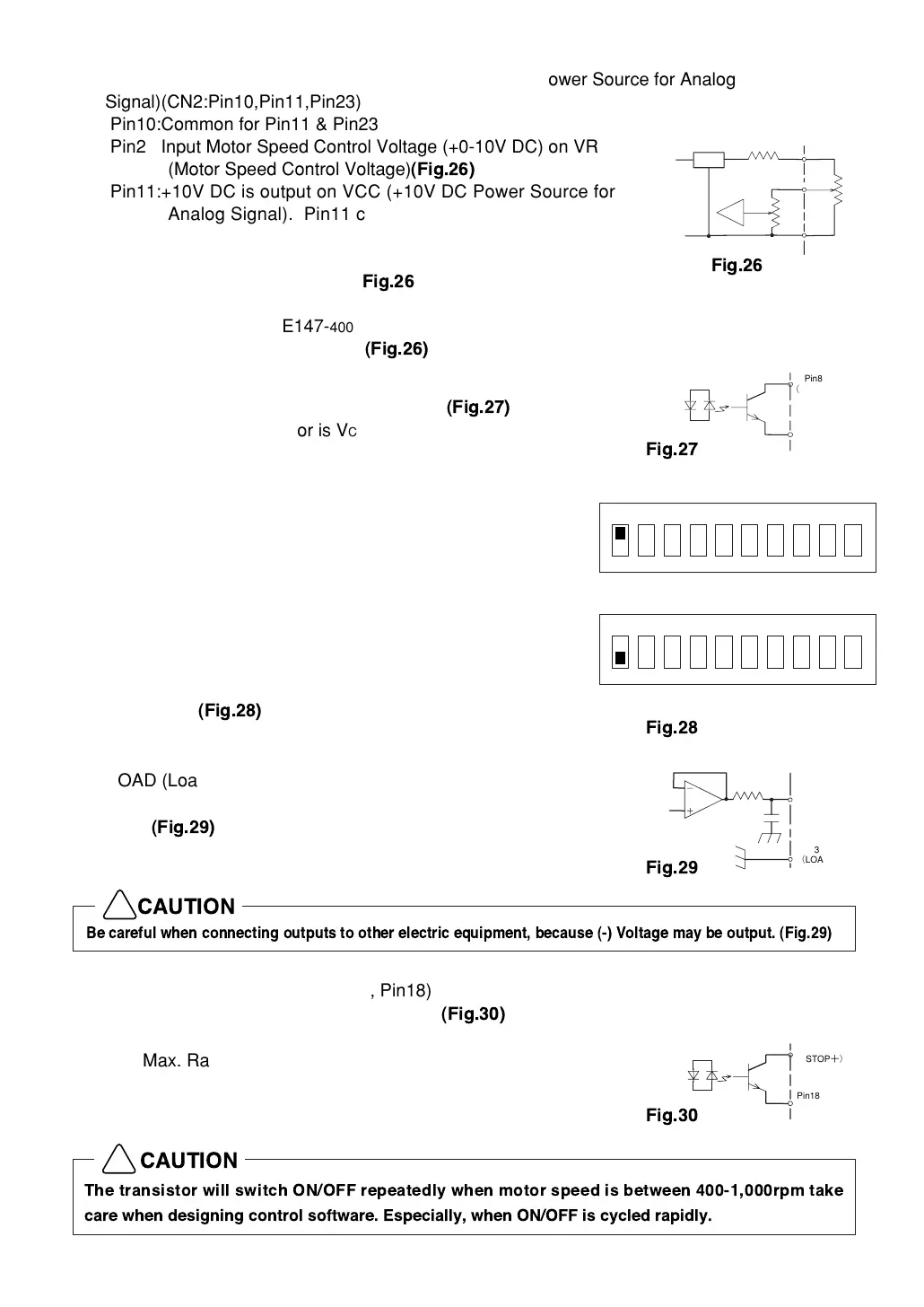
(2)VR(MotorSpeedControlVoltage)andVCC(+DC10VPowerSourceforAnalog
Signal)(CN2:Pin10,Pin11,Pin23)
Pin10:CommonforPin11&Pin23
Pin23:InputMotorSpeedControlVoltage(+0-10VDC)onVR
(MotorSpeedControlVoltage)
1
Pin11:+10VDCisoutputonVCC(+10VDCPowerSourcefor
AnalogSignal).Pin11canbeusedasasourceforMotor
SpeedControlVoltageandMotorSpeedRotationcanbe
variedbyvaryingthisvoltage.Attacha50KΩ
Potentiometer.(Referto
1
)
Bysupplying+10VDC,MotorSpeedcanbevariedupto
40,000min
-1
(NE147-400)・50,000min
-1
(NE147)or
80,000min
-1
(NE147-800)
1
.
1
Pin11
(VCC)
Pin10(GND)
Pin23
(VR)
+10V
Unitside+10V
Max
Min
50KΩ