9
Part 3. Checking/Adjusting the CO2
3. Checking/Adjusting the CO2 at
Minimum Gas Flow
(Low Fan Speed)
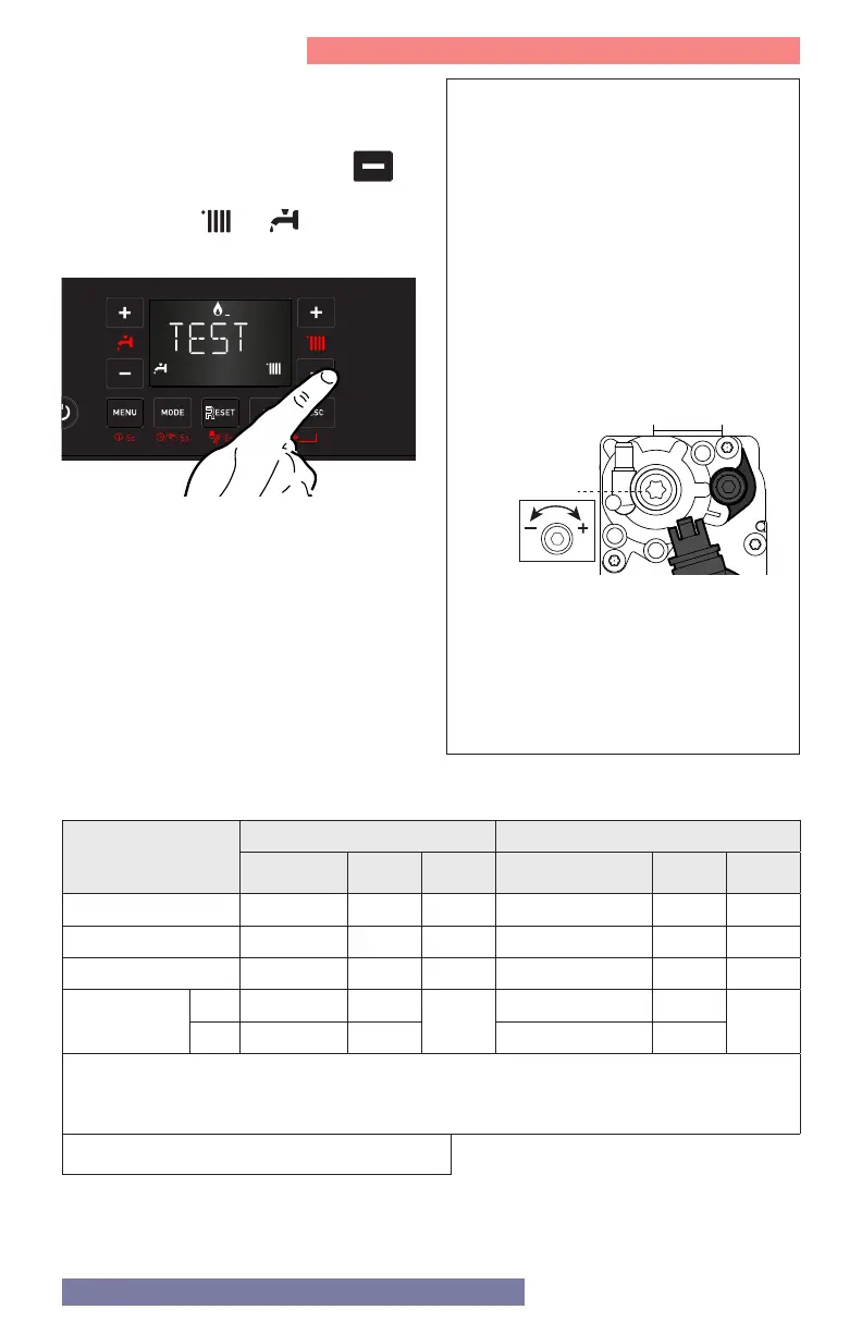
With Test Function active, press the
button to operate the boiler at minimum
DHW power. The
and icons will
display.
Wait 1 minute for the boiler to stabilize
before carrying out the combustion
analyses.
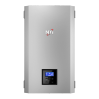
ADJUSTING THE GAS VALVE AT
MINIMUM GAS FLOW
Remove cap and adjust screw 2 by
turning counter - clockwise to reduce
the CO2 level; clockwise to increase the
CO2 level.
Wait 1 minute after each adjustment for
the CO2 value to stabilize.
WARNING! MINIMUM GAS FLOW
ADJUSTMENT IS VERY SENSITIVE.
If the value measured corresponds to
the value given in Table 3 adjustment
is complete. Otherwise continue the
setting procedure.
ATTENTION!! IF THE VALUE OF THE
CO2 AT MINIMUM POWER HAS
BEEN CHANGED, IT IS NECESSARY
TO REPEAT THE ADJUSTING AT
MAXIMUM GAS FLOW.
2
Figure 8 - Min CO2 Adjustment
If the CO2 (%) reading at min gas flow is
greater than the CO2 (%) reading at max
flow, or if it is less than the reading at max
flow by more than 1.0%, adjust the gas
valve following the instructions below.
Otherwise move directly to next operation.
Table 4 Minimum and Maximum Gas Flow
Model
Minimum Gas Flow Maximum Gas Flow
P.233 (%) RPM MBH P.234 / P.234 (%) RPM MBH
085 7 1504 8.5 78 6616 85
110 / 110C 11 1792 11.0 100 8200 110
150 / 150C 6 1432 15.0 91 7552 150
199 / 199C
NG 4 1288
19.9
91 7552
199
LP 6 1432 93 7696
1. Canada: Altitudes between 2000-4500 ft, de-rate by 10%. Consult local authorities for
de-rating for altitudes above 4500ft.
2.
USA: De-rate capacity by 4% for every 1000 ft above sea level, if altitude is above 2000 ft.