Patent applied for.
AIRE-VOLVE TWIN FANS
(AVT/AVTCP) Direct Drive,
Run & Standby
Fans for External use
Installation and Maintenance
1
16. 03. 18. Leaflet Number 671590
The EMC Directive
2014/30/EU
The Low Voltage
Directive
2014/35/EU
1.0 Introduction
Units are rectangular in section and incorporate a full size
hinged access panel fitted to the top of the unit for inspection
purposes.
The models are coded as follows:
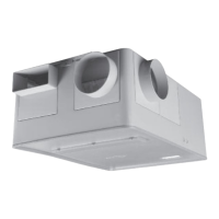
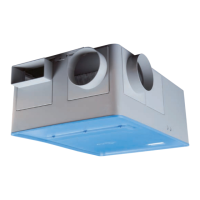
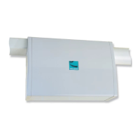
AVT-X (External/Internal Duct Mounted) in line unit.
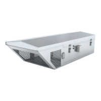
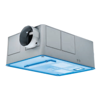
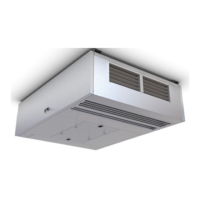
AVT-R (Roof Mounted, end inlet) side discharge unit.
AVT-X units are rectangular in section and have circular rigid
spigots at each end.
AVT-R units are rectangular in section and are supplied with
a circular end spigot and an individual module with two opposed
side discharge grilles.
2.0 Handling
Upon receipt of the equipment an inspection should be made.
Before commencement of lifting ensure that normal equipment
safety checks have been carried out.
The unit/sections should be removed from the vehicle using
a fork lift or crane. Always handle with care to avoid damage
and distortion, and where lifting slings are employed use
spreaders to ensure slings do not come into contact with the
unit case, or control pack.
Correctly position slings to avoid twisting of the unit case
and observe the centre of gravity before the final lift is made.
Note: the weight of the unit from the rating plate.
Dependent on model and size units may be supplied in single or
multi-modular sections. Handle each section individually do not
stack for lifting or storage.
3.0 Installation
Installers - please note that installation must be carried out
by competent personnel in accordance with the appropriate
authority and conforming to all statutory and governing
regulations e.g. I.E.E, CIBSE, COHSE. HSG33.
AVT-X/R units are suitable for internal or external use.
The unit can be mounted at a maximum angle of 20 degrees
from horizontal with the units discharge blowing downwards
away from the roof ridge. The unit cannot be vertically mounted.
Units should always be positioned with sufficient space to
allow the access cover to open and subsequent removal of fan
and motor assemblies etc.
Whether internally or externally mounted, the method of fixing
to the roof is the responsibility of the installer.
All units have a bottom skirt to allow for fixing directly onto a
suitably sized curb or builders upstand. Nuaire can supply
matching adjustable leg supports. Ductwork connections must
be airtight to prevent any loss of performance.
3.1 Fitting the grille section, module
Fig. 1a. Remove spigot outlet by removing end panel fixings, and
release from gutter section (upward motion).
Fig. 1b. Disassembly fixing bracket(s) and fit to main unit using
M6 fixing points provided & locate grille assembly onto unit.
Note: grille section is to be lowered (hooked) over guttering of
unit.
Code descriptions
1. Aire-Volve Twin Fan range
2. Constant Pressure option
3. Case sizes 1 to 9
4. Spigot configuration
AVT - CP 1-X
||||
1234
Fig. 1c. Ensure fixing brackets
halves are correctly aligned
and assemble using M8 Cap
head bolt and nut supplied
with bracket.
Fig. 1d. Once located, tighten
bolts ensuring seal between
grille and seal is achieved.
Airflow
Fixing bracket
halves
Nuaire: A Trading Division of Polypipe Limited Western Industrial Estate Caerphilly United Kingdom CF83 1NA
T: 029 2088 5911 F: 029 2088 7033 E: info@nuaire.co.uk W: www.nuaire.co.uk