Nuaire Limited Western Industrial Estate Caerphilly United Kingdom CF83 1NA
T: 029 2088 5911 F: 029 2088 7033 E: info@nuaire.co.uk W: www.nuaire.co.uk
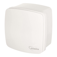
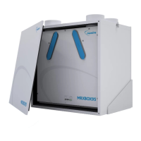
DRIMASTER 2000
and DRI 2000-3S
Anti-Condensation & Whole House Ventilation Unit
Installation and Maintenance
Important notes to installers
The Nuaire Drimaster range has been curing severe condensation
problems for over 20 years in some of the worst affected
properties throughout the world.
Its successful operation depends entirely upon the unit being
installed strictly in accordance with these instructions.
We would, therefore, respectfully suggest that you read through
this guide in its entirety before commencing installation and then
go through this guide step by step to ensure a satisfactory
completion.
Whilst the installation of the Drimaster unit may be achieved by a
suitable craftsman, the provision of the electrical supply and the
connection of the unit to the mains must be carried out by a
qualified electrician.
The unit has a 5 year warranty starting from the day of delivery and
includes parts and labour for the first year. The remaining 4 years
covers parts only. This warranty is conditional on the following:-
a) That the unit is installed strictly in accordance
with this guide.
b) That the unit filters are removed and cleaned or
replaced at the recommended intervals.
c) If a floor is higher than 4.5m the requirements in sections
3.2 and 8.1 must be followed.
The unit represents a significant financial outlay on the part of the
user/specifier and the unique 5 year guarantee is important to them.
We make a point of advising them that the installer is provided with
detailed instructions regarding installation/guarantee registration
and therefore has the responsibility of ensuring that the unit is
guaranteed for the user/specifier.
Operation
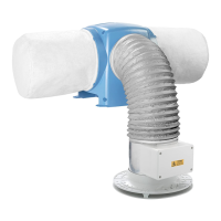
The Drimaster provides whole home ventilation using the Positive
Input Ventilation principle. Essentially the concept is to introduce
fresh, filtered air into the dwelling at a continuous rate, encouraging
movement of air from inside to outside.
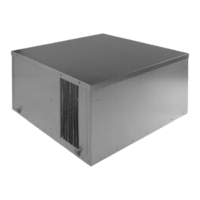
To achieve this, the unit is mounted in the loft space, drawing air
through the filters and inputting it, at ceiling level, into the property.
The Drimaster units are supplied with a remote temperature sensor
that works in conjunction with the units internal sensor. This sensor
continuously monitors the temperature in the loft and house,
boosting the air volume when the loft temperature is greater than
the house (heat recovery mode).
If the loft temperature becomes excessive the unit will switch to
standby mode (no airflow). Once installed, the airflow can be set to
suit the house size and, if required, the way it responds to the
temperature changes within.
1.0 Loft Inspection
Check to ensure that the loft has adequate ventilation. Look for
ridge vents, tile vents, eaves vents and continuous air gaps etc.
making sure none are blocked. In older properties these vents may
not be provided. However, there should be enough ‘leakage’ to
accommodate the requirements of the Drimaster unit. A useful way
of checking such lofts is to close the hatch, switch off the lights
and look for any daylight penetration. If you can see daylight it is
reasonable to assume that the loft has ventilation.
There may be occasions where a loft is so well sealed that additional
ventilation may have to be provided by the owner/occupier. This will
not only assist the operation of the Drimaster, but will help prevent
possible expensive structural damage caused by inadequate air
movement in the loft itself. It should be noted that there cannot be
too much ventilation into the loft.
Ensure that all water tanks are covered and sealed.
Check that all water pipes are lagged.
Ensure that any extract fans are discharging to outside and
not into the loft.
Check that the loft hatch is tightly sealed.
Ensure that all holes in the ceilings are sealed i.e. ceiling light
fittings etc.
A visual inspection of any flues or chimneys for leakage in the
loft should be carried out by the installer.
If any leakage points are found, or if there is any doubt at all,
then the installer should advise the house owner/provider as
soon as possible and seek instruction from them before
proceeding with the installation.
2.0 Siting the Diffuser position
The diffuser has a unique air throw pattern and it is essential that it
is located correctly in the central hallway in single story properties
or in the ceiling of the top floor landing on 2 or more storey dwellings.
As can be seen in figure 2 the diffuser discharges air evenly from all
four sides along the underside of the ceiling.
Figure 2. Diffuser (viewed from below).