Note: SMOKE ALARMS
It is also important to ensure that the diffuser is NOT placed within
1 metre of a smoke alarm.
If the diffuser cannot be repositioned, two sides of the diffuser
must be closed off using the foam strips supplied to encourage the
air through the remaining open sides that faces at least 1.5 metres
of unobstructed area away from the smoke alarm sensor.
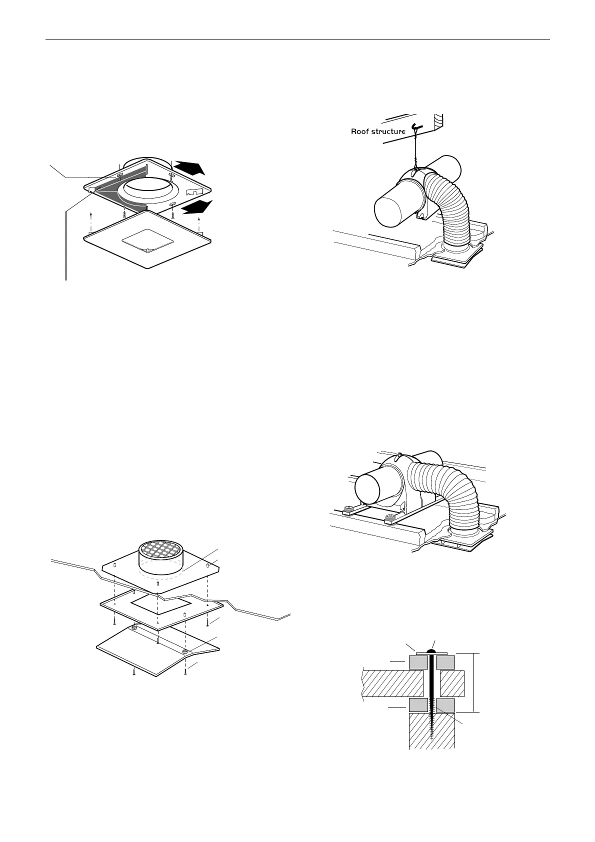
Figure 3. Fitting the 2 foam strips.
3.0 Fitting the Diffuser
3.1 Plastic Type
Cut a circular hole 225mm diameter in the ceiling between two
convenient joists. Position the diffuser frame and secure it to the
underside of the ceiling with the 1
1
/2
“ x 8 csk. hd. screws and plugs
provided.
Attach the diffuser plate to the frame using the four built in press on
clips provided. Foam strips should also be used as required when
this method of installing the diffuser is used.
3.2 Painted aluminium type c/w intumescent
fireblock
Cut a 200mm hole in ceiling and align the top portion of unit (A)
above the ceiling over the hole.
Position the central ceiling plate (B) on the ceiling in the room
ensuring the the central hole is aligned with thehole in the ceiling.
Use the 4 MS X 35mm screws to fix (B) to (A) through the 4 studs
positioned on the upper side of (B).
Screw bottom part of the unit (C) to the the ceiling plate (B) through
the plastic spacers and into the 2 studs positioned on the upper
side of (A).
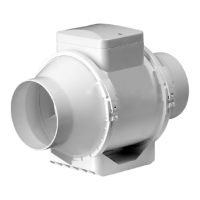
4.0 Fitting the filters to the unit
The filter has a push fit rim to attach itself to the main body of the
unit.
Offer the filters up to the unit and apply a small amount of pressure
to the filters rim (by hand). The filter will clip into place.
The unit can then be attached to the roof via the chain (or fixed to
the floor joists using the optional anti vibration mounting kit).
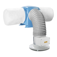
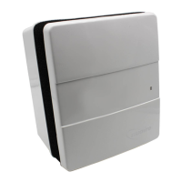
5.0 Fitting the Drimaster Unit
The standard method of installation is suspended from a convenient
roof beam via the cord/chain supplied.
(Note: unit weight = 3.2 kg).
The method of locating the wire to the roof timber is the responsibility
of the installer.
The flexible ducting fitted to the fan unit is connected to the outlet
diffuser spigot by securing the end over the spigot using the tie
band supplied. Ensure all duct joints are air tight.
6.0 Optional AV mounting
The AV kit contains all the parts necessary to complete a joist
mounted installation. If this option is required the kit can be
purchased direct from Nuaire using the following code number:
771393.
Lower the unit with the battens attached onto the joists (see
Figure 6). Mark and drill the 12mm dia. clearance holes required in
the ends of the battens (not supplied). Figure 7. shows a sectional
view of the fixing.
Place anti-vibration mounts above and below each batten fixing
point and, using the 4 large screws and special washers, fix the unit
to the joists.
Do not overtighten the fixings. The distance from the top washer
to the joist when installed must not be less than 50mm.
2
Leaflet Number 671109 November 2011
Installation and Maintenance DRIMASTER 2000/2000-3S Anti-Condensation & Whole House Ventilation Unit
 Loading...