Do you have a question about the NuAire Ecosmart ESTCP and is the answer not in the manual?
Details on ESTCP-X/ESXCP-X (in-line) and ESTCP-R/ESXCP-R/ESTCP-B/ESXCP-B (roof mounted) unit configurations.
Instructions for careful handling to avoid damage and distortion during unit manipulation.
Guidance on competent installation, unit positioning, and ductwork connections.
Details on using prefabricated curbs and roof upstand mounting for secure unit placement.
Methods for managing static pressure at the fan inlet for optimal system performance.
Covers control module connections, signals (fault/run), damper connections, and data cable installation.
Technical data for fan motors including speed, power, current, fuse ratings, and operating pressure.
Explanation of LED indicators on the control panel and response to BMS signals.
Procedures for adjusting maximum/minimum fan speed and system operating pressure.
Recommended maintenance schedule and confirmation that motors have sealed-for-life bearings.
Steps for cleaning the fan unit exterior, interior, fan, and motor assemblies.
Guidance on replacing fan/motor assemblies and details of the 5-year warranty.
Contact information for technical assistance, spare parts, and product information.
Formal statement regarding machinery assembly and conformity with EC directives.
Comprehensive information for safe installation, commissioning, operation, and maintenance.
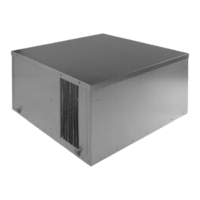
The Nuaire range of constant pressure direct drive external units comprises single and twin-fan models, designed for duties up to a maximum of 1.5m³/s. Twin-fan units incorporate run/standby and auto changeover features, while single-fan units have one fan only.
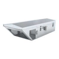
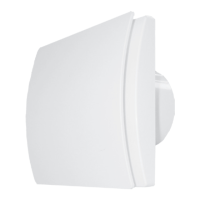
The ESTCP-X and ESXCP-X models are 'in-line' units, supplied with rigid circular spigots at each end, making them suitable for external and internal duct-mounted applications.
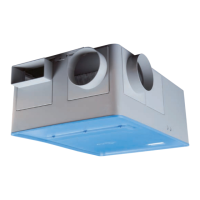
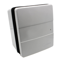
The ESTCP-R and ESXCP-R models are supplied with a rigid circular inlet spigot and two opposed side discharge spigots, designed for external roof-mounted applications.
The ESTCP-B and ESXCP-B models are supplied with a rigid circular inlet spigot and two opposed side discharge spigots, also suited for external roof-mounted applications.
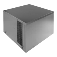
The casings are constructed from heavy gauge 'Aluzinc' aluminium and zinc-coated mild steel. Full-size access panels are fitted to the top of the units, which are fully detachable for inspection and connection purposes. The units incorporate two independent motors with high-efficiency, centrifugal impellers running in metal scrolls.
The motors are manufactured to BS 5000 and are suitable for single-phase supply. Airflow and failure monitors are standard, as is Class B insulation. The units are suitable for operation in ambient temperatures up to 40°C.
Ecosmart constant pressure extract fans are supplied to control the static pressure at the fan inlet. This setup is suitable for the majority of applications. However, when ancillaries with high pressure losses are fitted to the fan's inlet side, the low pressure tapping needs to be moved from the fan chamber to a location upstream of the ancillaries. Failure to do this will result in excessive pressure being applied to the dampers at the rooms when the system is running in trickle mode.
The fan's response to a 0-10V dc BMS signal is given in the following table. The BMS signal will override any sensors and user control connected in the system.
Handling: Handle the units carefully to avoid damage and distortion. If mechanical aids are used to lift the unit, spreaders should be employed and positioned so as to prevent the slings, webbing, etc., from making contact with the casing.
Installation: The installation must be carried out by competent personnel in accordance with the appropriate authority and conforming to all statutory and governing regulations. The units are suitable for internal or external use. All units can be installed at any angle up to 60°. However, on a sloping roof, the unit must be blowing upwards toward the roof ridge to ensure correct backdraught shutter operation.
Units should always be positioned with sufficient space to allow removal of the access cover and subsequent removal of fan and motor assemblies. Whether internally or externally mounted, the method of fixing is the responsibility of the installer.
All units have a bottom skirt to allow for fixing directly onto a suitably sized curb or builders upstand. Nuaire can supply a matching prefabricated curb for these units. Ductwork connections must be airtight to prevent any loss of performance.
All units have an internal connection box requiring connection to the mains supply on installation. It is the installer's responsibility to drill the case to provide access for the electrical cables. Care should be taken not to damage internal components, and the cable entry should be properly sealed.
A commissioning box is provided on the outside of the case. The unit should be securely screwed to its curb or mounting to prevent vibration and/or wind damage. Note that on the bottom inlet (ESTCP-B/ESXCP-B) units, the cabling could be carried up from inside the building through the bottom inlet spigot.
Prefabricated curbs, manufactured in pre-galvanised steel, reduce design work and guarantee correct unit mounting on site. The upper faces of the curb are fitted with a robust sealing strip.
Roof Upstand Mounting: The fan casings have an inside skirt depth of 60mm or, in the case of the largest size units only, 50mm. It is recommended that the units are mounted upon a suitable curb or upstand which has a minimum height of 150mm (inclusive of the timber capping if applicable). This mounting height provides adequate distance to avoid any standing water on the roof being drawn into the fan (this can occur on bottom inlet installations if a unit is not properly installed and an air leak in the unit/ductwork joint is pulling air over the curb). The recommended height will also ensure that the unit does not 'stand' on its skirt edge.
Electrical Details: Before commencing work, ensure that the unit, switched live, and Nuaire control are electrically isolated from the mains supply. An Inverter is used to provide speed control. When the fan is isolated, allow 5 minutes for the capacitors in the inverter to discharge before commencing any work on the unit. If an RCD is fitted to protect the circuit, a type B RCD should be used (trip limit 300mA). Otherwise, nuisance tripping will occur.
The 4 IDC plug-in connectors are provided for the connection of compatible sensors, manual controls, and for linking the fans together under a common control. If more than 4 connections are required, a junction box should be used. A signal of 100-230V a.c. will activate the fan. Note that a signal from an isolating transformer will produce an unpredictable result and is not recommended.
Volt Free Relay Contacts: The volt free contacts are not fused. If these are used to power any external equipment, the installer must provide adequate fusing or other protections. These contacts are rated at 5A resistive, 0.5A inductive.
Run connections: These contacts are closed when the fan is running. Fault connections: No fault = the contacts are closed. Fault = the contacts are opened (this includes no power supply at the unit).
Data Cable Installation: A 4-core SELV data cable is used to connect devices such as sensors to the fan and for interconnecting multiple fan units. Do not run data cable in the same conduit as the mains cables and ensure there is a 50mm separation between the data cable and other cables. The maximum cable run between any two devices is 300m when it is installed in accordance with the instructions. Please note that the total data cable length used in any system must be less than 1000m. Keep the number of cable joints to a minimum to ensure the best data transmission efficiency between devices.
Maximum Number of Devices: The maximum number of devices (including fans) that can be connected together via the data cable is 32, irrespective of their functions.
Any other low voltage/signal cable connection (BMS): Follow the guidelines as given in 'd' and keep the cable length as short as possible - less than 50m.
Testing after Installation: Ensure that the Fan unit and any specified controls are fitted securely according to the instructions. Switch on the mains supply. Push the test button to run each fan and check that they run satisfactorily. If a switched live signal is used, activate this signal and check that the fan runs. De-activate the switched live signal and check the run-on-time; adjust if necessary. Adjust the maximum and minimum airflow (if required) by following the instructions on page 4.
Using the Test button: The test button allows the individual blowers within the unit to be checked for its operation. If the fan is running already, press the button once to stop the fan, press again to switch on the standby fan, press again to stop and so on. Note that the fan will return to normal operation after 30 seconds.
Maintenance Intervals: The first maintenance should be carried out three months after commissioning and thereafter at twelve-monthly intervals. These intervals may need to be shortened if the unit is operating in adverse environmental conditions, or in heavily polluted air. Note: failure to maintain the unit as recommended will invalidate the warranty.
Lubrication: Motors are fitted with sealed-for-life bearings and do not require any lubrication.
General Cleaning and Inspection: Clean and inspect the exterior of the fan unit and associated controls, etc. Remove the access panel from the fan unit. Inspect and, if necessary, clean the fan and motor assemblies and the interior of the case. If the unit is heavily soiled, it may be more convenient to remove the fan/motor assemblies.
Check that the shutters are free to move smoothly and that they seal the appropriate fan outlet effectively. Clean and inspect each fan and motor assembly as follows, taking care not to damage, distort, or disturb the balance of the impeller:
Refit the assemblies to the unit (see Replacement of Parts) then replace the access covers. If Nuaire controls and/or remote indicators are fitted, remove the covers and carefully clean out the interiors as necessary. Check for damage. Check security of components. Refit the access covers.
Replacement of Parts: The only item of the fan units unit likely to require replacement are the fan/motor assemblies due to a failed motor or damaged impeller. In either eventuality, the complete fan/motor assembly must be removed from the unit case. Note: before commencing work, electrically isolate the fan unit and/or the associated Nuaire control, if fitted, from the mains supply.
Remove the access cover. Disconnect the incoming wiring from the connection box (located on the fan scroll) on the particular fan/motor assembly to be removed. Support the weight of the fan/motor assembly and remove the mounting screws and washers. Lift the assembly out of the case. After replacing the faulty item, refit the fan/motor assembly and reconnect the incoming wiring to the fan-mounted connection box. Replace the access cover.
Spare Parts: When ordering spares, please quote the serial number of the unit together with the part number. If the part number is not known, please give a full description of the part required. The serial number will be found on the identification plate attached to the unit casing.
Warranty: The 5-year warranty starts from the day of delivery and includes parts and labour for the first year. The remaining period covers replacement parts only. This warranty is void if the equipment is modified without authorisation, is incorrectly applied, misused, disassembled, or not installed, commissioned, and maintained in accordance with the details contained in this manual and general good practice.
| Category | Fan |
|---|---|
| Housing Material | Galvanized Steel |
| Motor Type | Electronically Commutated Motor (ECM) |
| Wheel Material | Aluminum |
| Energy Efficiency | High efficiency ECM motor |