ES-LCD is a new range of user control
from the Ecosmart range.
They have a 3.5in colour LCD touchscreen
display to provide improved user interface.
The unit can be surface or semi-recess
mounted and is compatible with standard
2-gang recess back box.
ES-LCD– the unit is all plastic construction
and supplied with 10m of pre-plugged
connection cable and surface mounting
back box.
It is supplied with 10m of pre-plugged
connection cable and surface mounting
back box.
The units are SELV (12V d.c.) with the
power supplied from the fan unit via the
pre-plugged cable.
1.0 Installation
Installed environment
0-40
o
C and up to 90% RH non-condensing.
Caution: The unit must be installed away
from any direct source of heat (e.g.
radiators) and not in areas where it
would be subjected to steam or water
spray.
The mounting surface must be free
from vibration.
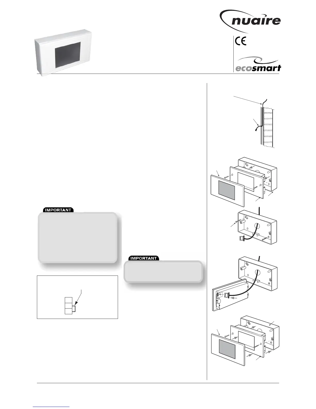
The unit is supplied with back box suitable
for surface mounting. (see Figs. 1 - 5).
If semi-recess (final projection from wall
is 7mm approx) is needed, a proprietary
2-gang back box (25mm deep min.) may
be used.
Always physically check the suitability of
the back box before fitting.
In some instances, the earthing point of
the back box may foul the unit and need to
be removed.
a) Fix one end of the 10m cable to the
fan’s connection box (connection sockets
marked NET, see Fig. 1) and route the cable
to the mounting position.
b) Unclip the front bezel from the unit and
remove the 2 retaining screws, then
remove the working section from the back
box. (see Fig. 2).
c) Feed the cable through the knock-out
hole in the base of the back box and mark
the fixing point on the wall.
Drill appropriately sized holes at the fixing
points and insert the wall plugs.
Fix the back box on to the wall. (see Fig 3).
d) Plug the data cable into the sock
et.
(see Fig. 4).
e) Fix the unit back into the back box
using the screws supplied, then clip the
bezel back on the unit again noting which
way is up. (Top is printed on the inside face
of the bezel and and middle section).
(see Fig. 5)
2.0 Data cable installation
A 4-core SELV data cable is used to
connect the control to the fan.
Do not run data cable in the same
conduit as the mains cables and ensure
there is a 50mm separation between
the data cable and other cables.
Please note that the total data cable
length used in any system must be less
than 1000m. Keep the number of cable
joints to a minimum to ensure the best
data transmission efficiency between
devices.
 Loading...