XBOXER XBC 10-65 Ecosmart Connect (CO) Control
nuaire.co.uk 029 2085 8200
6.0 Installing the XBC Fan Units and Attenuators
The ventilation unit must be installed first–with consideration
made for the length of the associated attenuators.
Installation of the XBOXER XBC units, including all external services
and controls should be installed in accordance with the appropriate
site procedures, and MUST conform to all governing regulations e.g.
CDM, CIBSE, IEE, and in strict accordance with the applicable Building
Regulations.
The correct installation position for the units shall be decided with due
regard to access and maintenance requirements, and the objective of
minimising the system ductwork resistance.
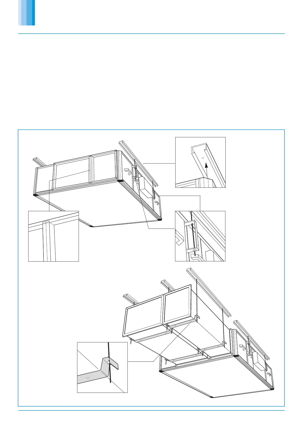
The recommended installation method is to use standard Unistrut
channel secured to the slab / steelwork above the unit.
Four suitable drop rods should be secured to the Unistrut channel and
extended to be fixed to the unit’s four mounting brackets, (two each
side of the fan unit) or to other horizontal supports by others where
wider load distribution is required.
6.1 Installing the Attenuators
It is recommended that additional Unistrut channels are used to
support the matched attenuators. M8 Drop rods should be secured to
the Unistrut channel and extended to be fixed to the four piece support
brackets to be used on the underside of the attenuators (see Figure 14).
Note – once the attenuators are supported and levelled, and
immediately before securing the attenuator to the attenuator flange
connector, remove the backing from the Foam Sealing Strip.
The attenuators must be secured to the unit using the screws provided.
1. Secure standard Unistrut channel to the slab/
steelwork above the attenuators.
2. Secure M8 drop rods from the Unistrut channel
into position.
3. Raise up the attenuator into position and attach
the four piece support brackets onto the drop rods.
(2 on each attenuator).
4. Utilising the 2 x 5.6mm dia holes in each bracket
use relevant self tapping screws to fix into position
on the underside of the attenuators.
5. Immediately before
securing the attenuator
to the connector, remove
the backing from the
Foam Sealing Strip.
6. Secure the attenuators
to the attenuator flange
connector on the end of
the fan unit. (see fig 10).
2. Secure the four drop
rod suspension system
from the Unistrut channel
into position through the
fan unit’s mounting
brackets. (2 each side of
the unit, see bracket
positions page 4).
1. Standard Unistrut
channel secured to the
slab /steelwork above
the unit.
The attenuators are secured to the fan unit using
the attenuator flange connector on each end of
the fan unit when the recommended installation
procedures in fig 10a have been completed
(compatible with 20mm Mez).
Four piece support brackets.
Figure 13. Installing the fan unit.
Figure 14. Installing the unit attenuators.
 Loading...