XBOXER XBC 10-65 Ecosmart Connect (CO) Control
nuaire.co.uk 029 2085 8200
2.0 XBOXER XBC Unit Access Concepts
In this product range, several unique concepts have been
implemented with a view to simplifying the installation design.
1. The unit configuration is such that the supply and discharge
connections are positioned on the unit centre line.
The corresponding Intake and Extract connections may be positioned
on either side of the unit, allowing greater flexibility in the layout of
ductwork in the space, (see Figure 3 - Figure 5) with the blanking panel
re-positioned to suit.
2. The standard Ecosmart XBC unit configuration is shown in Figure 4.
Unit handing information will not be requested for this range, and
units will be supplied in this format as standard.
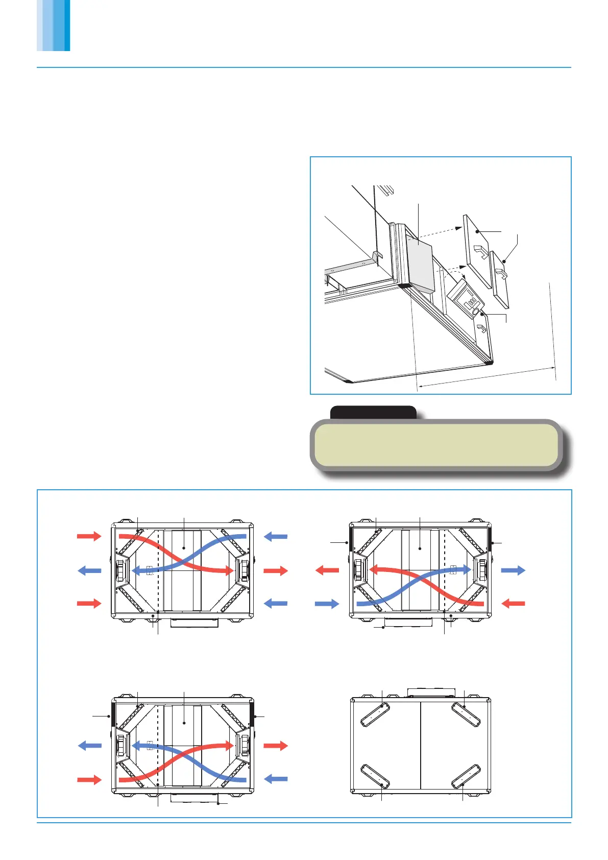
3. The unit must be installed with at least 250mm clearance from a
wall / barrier. With this absolute minimum clearance, the unit may
be connected to the power supply and control connections since the
control may be rotated by 90 degrees to face downwards.
(Note: - cable connections must allow for the relative movement when
the control is re-positioned).
4. With this clearance, unit filters may be changed, and the fans coils,
heat exchanger and condensate tray may be inspected and cleaned if
necessary.
5. The LPHW and Electrical heater settings, coil bleed and drain, and all
other control adjustments are similarly accessible (see Figure 1).
6. Side access, where possible, is preferred in all cases in terms of safe
working access to the equipment under the CDM regulations.
7. Note however, that access in the situation is difficult and does not
allow for major maintenance including component replacement. Nuaire
recommend as best practice guidance, to allow for a minimum of
around 600mm clearance (as stated in ADF 2010).
8. Where these arrangements are not suitable, the Consultant’s
and Contractor’s project specific requirements will always be
accommodated where possible.
250mm clearance for access
on control side
Access covers
of fan unit
& basic control
Hinged Ecosmart
to assist with
commissioning.
box rotates 90
o
internal frame
Filter removal from
Plan view
Extract
Counterflow Plate Heat Exchanger
Position 2.
Extract
Position 1.
Supply
Intake
(Fixed)
Position 1.
Intake
Position 2.
Discharge
(Fixed)
Filter
Plan view
Blanking
plate
Extract
Position 1.
Supply
(Fixed)
Intake
Position 2.
Discharge
(Fixed)
Filter
Blanking
plate
Coil connections
LPHW or Electric Heater Battery
Control
LPHW or Electric Heater Battery
Counterflow Plate Heat Exchanger
Filter access
Filter access
Filter access
Filter access
Plan view
Discharge Supply
(Fixed) (Fixed)
Extract
Position 1.
Blanking
plate
Blanking
plate
Intake
Position 2.
Control
Coil connections
LPHW or Electric Heater Battery
Filter Counterflow Plate Heat Exchanger
Note: The unit is shipped with four G4 filters in place, two of which are included as spares. For F7 filters contact Nuaire.
9. Bottom access only units (Example code: XBC15-H-LES BA), provide
access to filters only (see Figure 6).
Filter removal is not available from the sides on these units. Bottom
access units must be installed with the following minimum clearance
below the units. XBC15 = 225mm, XBC25 = 300mm XBC45 = 360mm.
Note: Bottom access is not available on XBC55 or XBC65 units.
Figure 2. The control side of the unit must be installed with at least
250mm clearance from a wall / barrier to gain access from the side.
Figure 3. Selectable Duct Connections (Top view).
Figure 4. Standard Unit Format (Top view).
Figure 5. Opposite unit arrangement (R) side access (Top view).
Figure 6. Bottom access only unit (Example code: XBC15-H-LCO-BA).
IMPORTANT
Unlocking an access panel is achieved by inserting a flat head
screwdriver into the locking latch groove and turning anti-clockwise
(1/4 turn), keys are neither required nor provided by Nuaire.
 Loading...