16
CHAPTER - IX
BLOCK DIAGRAM DESCRIPTION
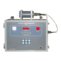
Area gamma monitor GA720 is shown in block diagram on the next page. It mainly consists of two parts.
(a) Detector probe with associated electronics &
(b) Main measuring unit with majority of µC based functional electronics & embedded code.
9.1 DETECTOR PROBE ELECTRONICS
This consists of energy compensated detector 71210 or its equivalent, with pulse processing electronics,
TTL to RS485 converter and +500V, HV module for detector biasing. Detector output signals generated from
RS485 transmitter chip are fed to main PCB through 5 pin I/O cable, connected to the Electronic unit.
These signals are received by RS485 receiver chip & counted by a 6 digit BCD counter in the main PCB.
The output of this counter is read by micro-controller continuously. The +5V power supply, required for HV
module and pulse processing SIL chip, generated on main board, is taken through a 5 pin I/O cable, to this
detector probe unit.
9.2 MAIN PCB CIRCUITS
Low voltage supplies +5V, +18V, & +5V
ISO
are generated through mains transformer, secondary & three
terminal regulator chips. All these supplies are used internally to power-up various circuits, for their functionality.
A four channel ADC reads fraction of HV & LVs & reports to micro-controller under program control to
indicate HV & LV failures if any to the user.
User interface to GA720 is through keypad command buttons EHT, PROG, INC, DEC, ACK & RESET.
These keys enable the user to configure & select various programmable options such as alarm set point,
unit of measurement, baud rate for communication, calibration factor & many more such functions etc.,
EEPROM serves as a memory device to store all the configured parameters including instrument ID etc.,
There are two visual displays provided (a) 16x2 LCD display & (b) 6 digit 7 segment LED display, driven by
multiplexed display driver. LCD display indicates all programmable functions & their values while programming
& it also indicates, dose rate, in acquisition mode (normal situation). ½ “ LED display indicates dose rate
in the selected unit (such as mR/hr or µSv/hr or cps or cpm)
The other interfaces to micro-controller include;
• Visual alarms (ACTIVE & NORMAL) cluster LED array GREEN & RED with their driver circuit to indicate
alarm & normal condition.
• A relay driver with relay PCB provides two sets of change over contacts for external use. This relay is in
energized condition in NORMAL condition of area gamma monitor & in de-energized state in ACTIVE
condition.
• For data transmission from area gamma monitor to SCADA, an RS485 interface has been built using TXD
& RXD pins of micro-controller. This facilitates area gamma monitors RS485 networking for data
communication. These RS485 signals have been brought out on a pair of 9 pin D-connectors (male / female)
for RS485 daisy chain connection of devices. Additionally these signals are made available on 17 pin also.
Most of the interfacing devices or circuits or peripheral chips are connected to micro-controller through I2C
bus, or ports or I/O expanders etc., for interfacing.
 Loading...