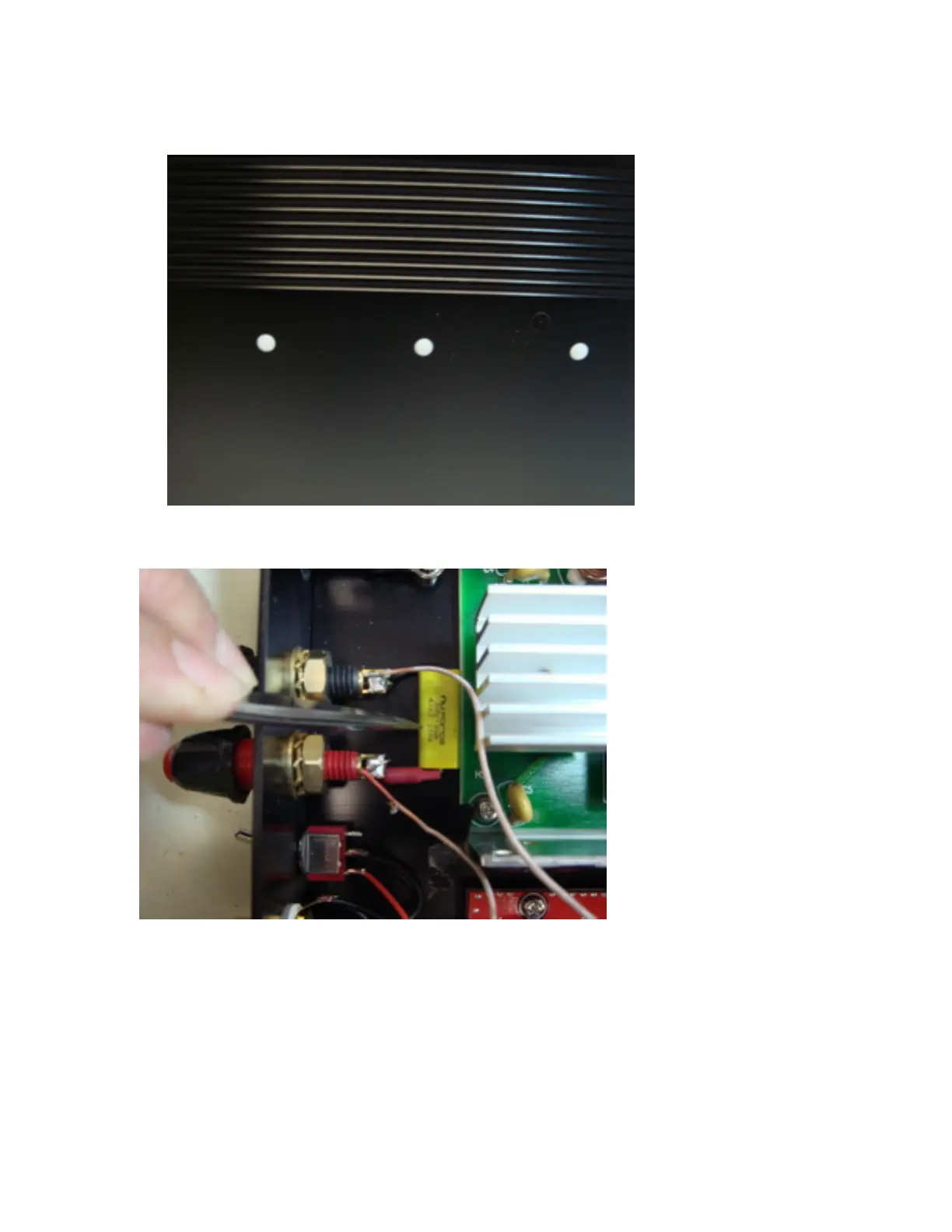
7. The 3 heat sink holes can be plugged with the included nylon covers. V2 heatsink is
not attached to the base of the chassis.
8. Install the new Zobel Filter under the speaker terminal and bend the leads so they are
against the speaker solder tab. Do not solder yet. (The Zobel filter is integral to the
operation of V2 and you must install it).
9. Solder the 3 input wires between V2 board and the connectors, according to the color.
White is Positive (+) signal, Red is Negative (-) signal, and black is Analog Ground.
XLR pinout: Pin1 – GND, Pin2-Positive, Pin3-Negative. **For reference only: 100-
ohm resistor between RCA Negative signal to XLR Ground. XLR Pin-3 (Negative) is