2
FIG. 1
FIG. 2
FIG. 4
634 OR 644
ROOF CAP
504
OPTIONAL 472 RE-
DUCER/DAMPER
505
FIG. 3
FIG. 5
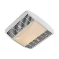
TYPICAL INSTALLATION
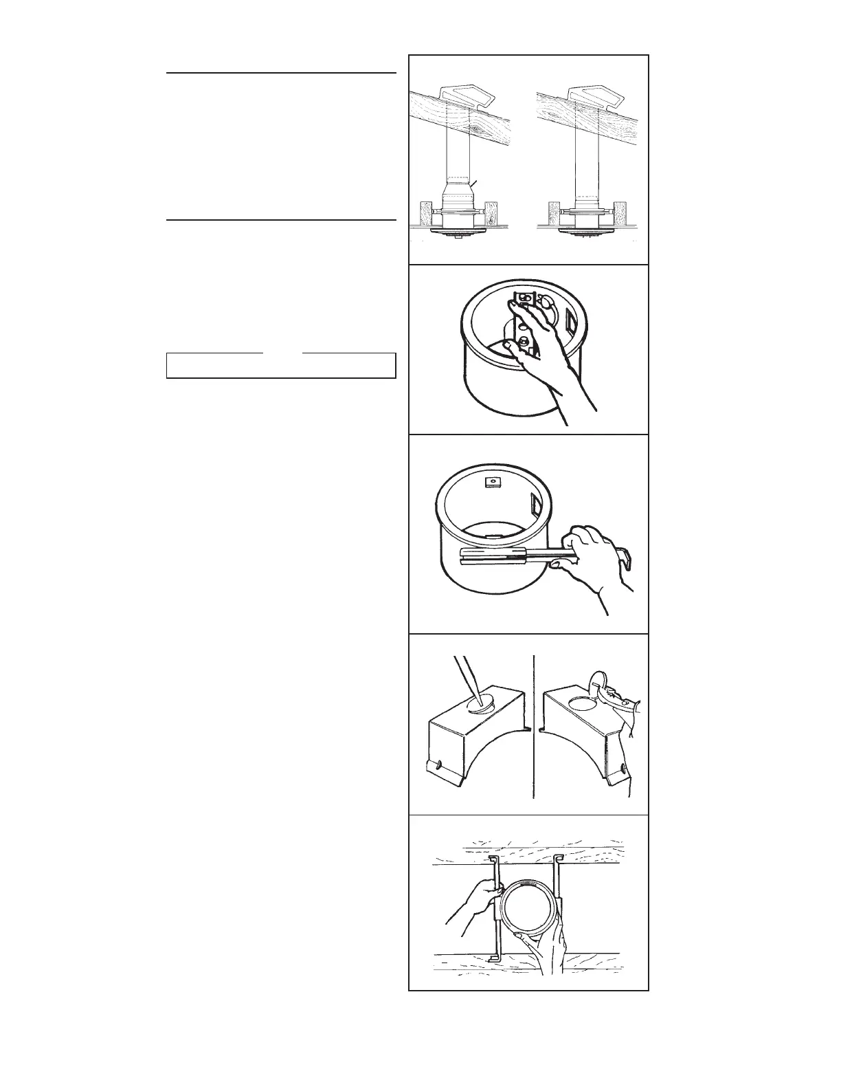
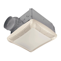
Fig. 1 shows typical installations.
Make sure that the selected location allows enough
vertical clearance above the fan to allow you to install
the ductwork.
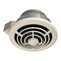
The Model 505 uses 8” diameter ductwork and has a
built-in damper.
The Model 504 uses 10” diameter ductwork.
Use the Model 472 Reducer/Damper with the 504 when
8” diameter ductwork is desired or when a damper is
needed.
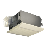
PREPARE THE FAN
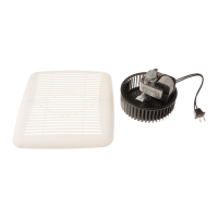
1. Remove motor assembly by loosening mounting
screws and rotating motor (FIG. 2).
2. Use care when handling motor bracket assembly
to prevent damage to blade. Do not set down as-
sembly with weight of motor resting on the blade.
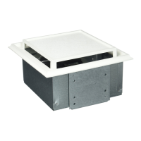
3. Slide adjustable mounting brackets into channels
on side of housing (FIG. 3). Brackets expand to fit
joists up to 24” on center.
4. Remove knockout from wiring box by breaking tabs
on knockout (FIG. 4). Remove bottom knockout.
NOTE
Remove bottom knockout ONLY!