Do you have a question about the NuTone N482BX Series and is the answer not in the manual?
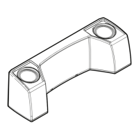
Mount the apartment speaker in NuTone rough-in or surface mount frame for installation.
Install necessary interconnecting wires and cables when rough-in frames are mounted.
Refer to NuTone Direct-A-Com Series 3 instructions for system wiring diagrams.
Connect each apartment speaker to the main entry via directory, mailboxes, or separate pushbuttons.
Use 3-twisted pair cable, common between amplifier and all apartment speakers.
Wire gauges and voltage for door release switch, transformer, and buzzer connections.
Run individual 18 gauge wire from each apartment pushbutton to the speaker buzzer.
Connect ORANGE, RED, and BLACK twisted pair cable to corresponding terminals.
Connect brown wires from buzzer and door release switch to transformer wire.
Connect brown wire from buzzer to individual pushbutton wire at main entry.
Connect brown wire from door release switch to DR-1 Electric Door Release wire.
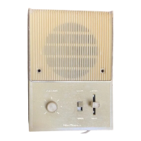
This document provides installation instructions for the NuTone Built-In Apartment Speaker, specifically models in the N482BX SERIES and DIRECT-A-COM 3. It covers general installation, multi-floor and garden apartment system wiring, and individual apartment speaker wiring, along with a limited two-year warranty.
The NuTone Built-In Apartment Speaker is designed for use in multi-floor and garden apartment complexes as part of an intercom system. Its primary function is to allow communication between individual apartments and a main entry point, often incorporating a buzzer for visitor notification and a door release switch for remote entry control. The system facilitates communication and access control within an apartment building environment.
The apartment speaker is designed for either built-in or surface mounting. For built-in installation, it should be mounted in a NuTone rough-in frame. For surface mounting, a NuTone surface mount frame is required. It is crucial to install all necessary interconnecting wires and cables when the rough-in frames are mounted. For detailed system wiring diagrams concerning optional Direct-A-Com 3 installations, users should refer to the Installation Instructions for the NuTone Direct-A-Com Series 3.
Each Apartment Speaker connects to a speaker at the main entry. The main entrance equipment can include:
The document emphasizes the importance of following the provided wiring diagrams and using recommended NuTone wire for optimal system performance and to ensure warranty validity. Product specifications are subject to change without notice.