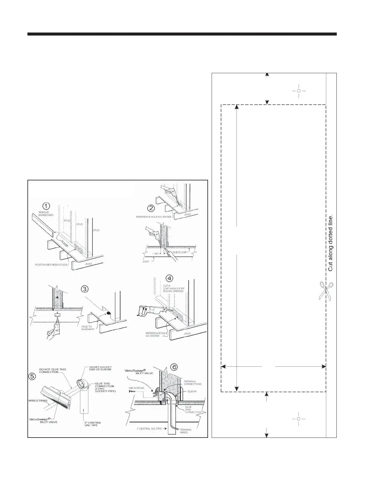
5. Glue the long socket of the tight elbow (part no. V382XS) onto a section
of 2” (51 mm) central vacuum tube. Make the terminal connections to
the VacuSweep Inlet Valve by sliding the low-voltage wire into wire
clips. Turn the power to the vacuum unit ON to test the connection.
After successful completion of the test, turn power to the vacuum unit
OFF. Wrap a piece of wire/string around the tubing. Using the
wire/string to temporarily hold the pipe and elbow in place, insert the
VacuSweep Inlet Valve into the opening at the base of the wall and
elbow. DO NOT glue this connection (Designed for friction fit). Refer
to Figure 26-5.
6. Remove the wire/string. With the door in an open position, secure the
VacuSweep Inlet Valve to the wall using no. 6 screws. Refer to Figure
26-6. Ensure that the spring on the electrical connector has
1/8” (3 mm) clearance to rough opening. Continue with remainder of
central vacuum connections. When the vacuum system is complete,
turn the power to the vacuum unit ON.
page 14
VacuSweep Inlet Valve Rough-in Template
VACUSWEEP
®
INLET VALVE INSTALLATION (CONT’D)
 Loading...