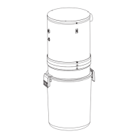
THE RANCH STYLE HOUSE
Here the power unit is mounted in the
garage. The intake and exhaust tubing,
the only exposed tubing in the installation,
runs up the garage wall and into the attic.
The trunk line runs horizontally through
the attic from the power unit to the
farthest inlet location. Branch lines
spread throughout the attic, connecting
the trunk line to the inlet tubing. Each
inlet tube is threaded vertically through
an inside wall. Located in hallways and in
large rooms, the inlets are placed to
provide maximum access to all cleaning
areas. Refer to Figure 1.
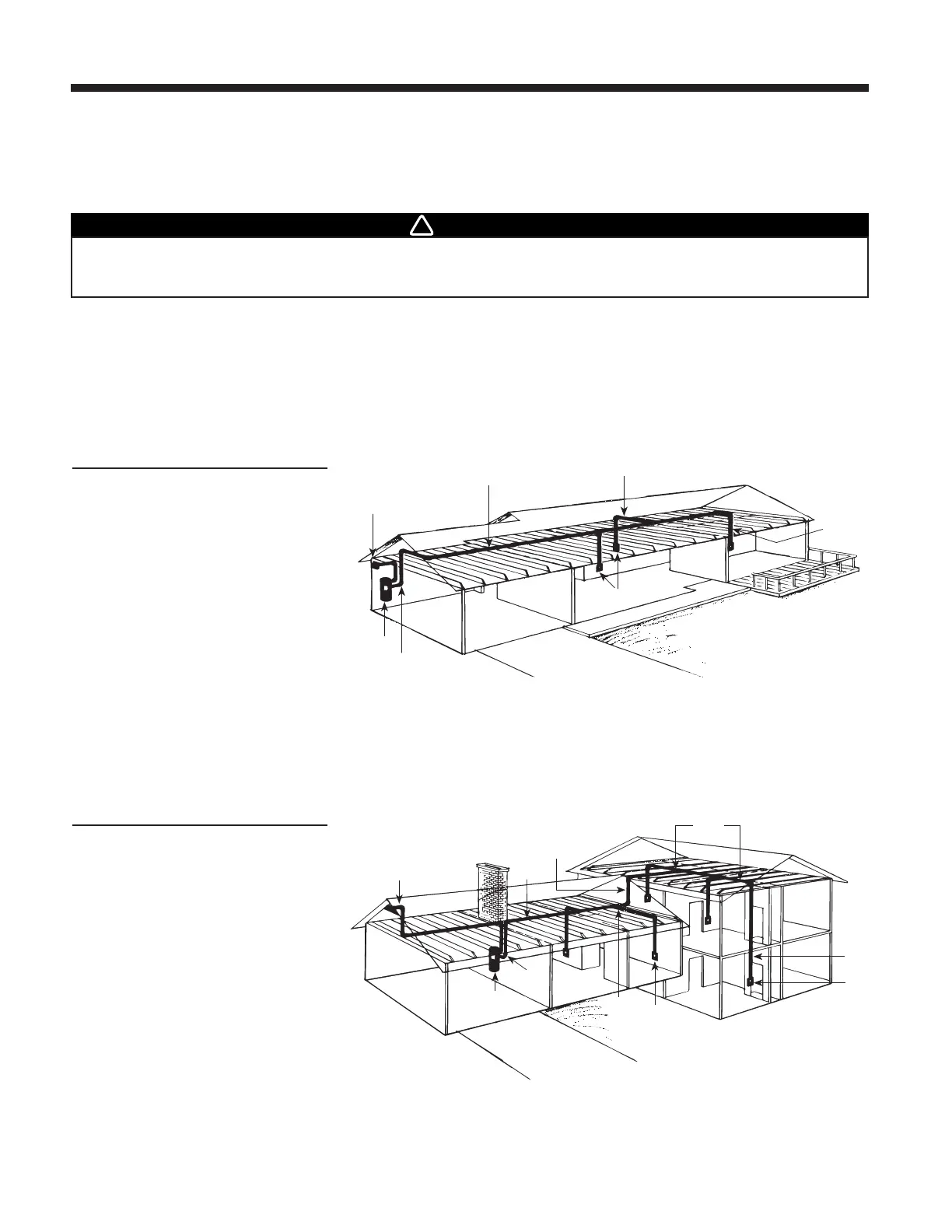
THE SPLIT-LEVEL HOUSE
Like the two-story house, the split level
installation commonly calls for a two-level
trunk line. Here, the power unit is located
in the garage. The intake tubing runs
exposed up the garage wall and into the
ground level section's attic. Two branch
lines connect this part of the trunk line to
inlet lines which are dropped inside
interior walls. A vertical branch line runs
to the upstairs attic, where the trunk line
branches into a T-shape. This trunk line
connects to two upstairs inlet lines and to
one inlet line which drops through an
upstairs wall and down into the third-level
utility room to service this entire level.
Refer to Figure 2.
FIGURE 2
page 2
SYSTEM PLANNING LAYOUT
Central Vacuum Systems consist of a Power Unit, PVC Tubing and Fittings, Wall Inlets, a flexible Hose and various cleaning
accessories.
The Power Unit is designed to be wall-mounted away from the living area of the home and connected to the living area by means
of permanently installed in-wall tubing, fittings and inlets.
Generally, an installation will require 3 to 4 inlets and 16 to 20 feet (4.9 m to 6.1 m) of tubing per inlet. It is suggested that a floor
plan be used to more accurately determine the quantity of materials needed.
Use the following examples as an aid in planning the installation in either new or existing construction. You should be able to
adapt the examples shown to your specific home layout.
WARNING
 Loading...