CONNECTION FROM BEHIND
Refer to Figure 25.
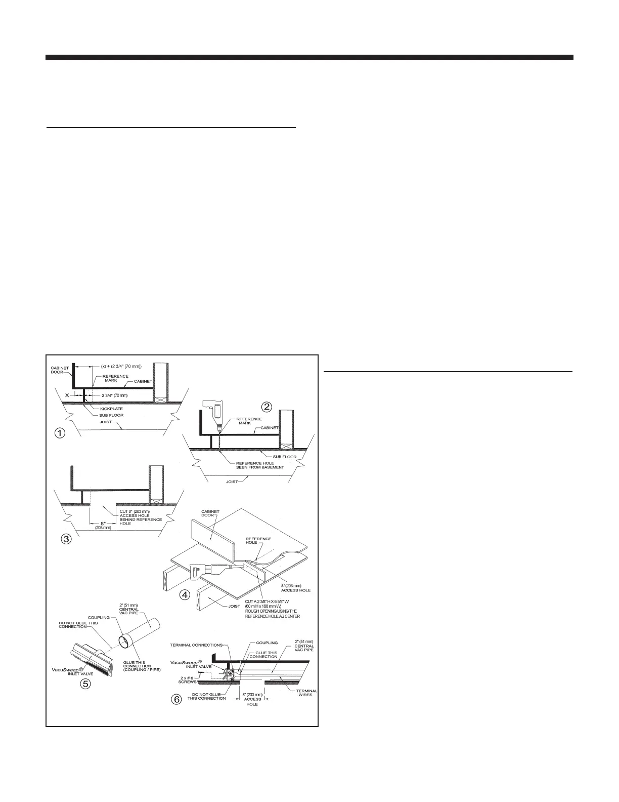
1. Turn the power to the vacuum unit OFF. Choose a location
under the cabinet for the VacuSweep Inlet Valve so that it
can be connected to the central vacuum tube. Measure
distance (X) between the kickplate face and the inside
edge of the cabinet. Then, add 2¾” (70 mm) to the
measured distance. Refer to Figure 25-1. Measure out the
new distance (X + 2¾” [70 mm]) from the cabinet door, to
the reference mark.
2. Drill a small reference hole straight down through to the
basement. Refer to Figure 25-2. Locate the reference hole
in the basement and verify that there are no obstructions.
3. Using a reciprocating saw, cut an access hole in the floor
under the cabinet and approximately 8” (203 mm) behind
the location of the VacuSweep Inlet Valve reference hole
so that the VacuSweep Inlet Valve can be connected to
vacuum tube by reaching through the access hole. Refer to
Figure 25-3.
4. Using the reference hole as a center, cut a 2⅜” H x 6⅝” W
(60 mm H x 168 mm W) rough opening in the kickplate
face. Refer to Figure 25-4.
5. Insert a coupling (part no. V127) onto the rear of the housing.
DO NOT glue this connection (Designed for friction fit).
Refer to Figure 25-5. Make the terminal connections to the
VacuSweep Inlet Valve by sliding the low-voltage wire into
wire clips. Turn the power to the vacuum unit ON to test the
connection. After successful completion of the test, turn
power to the vacuum unit OFF. Insert the VacuSweep Inlet
Valve into the cabinet base and tube.
6. With the door in an open position, secure the VacuSweep
Inlet Valve to the cabinet base using no. 6 screws.
Refer to Figure 25-6. Ensure that the spring on the electrical
connector has 1/8” (3 mm) clearance to rough opening.
From the basement reach through the access hole and
glue a section of 2” (51 mm) central vacuum tube to the
coupling. Continue with remainder of central vacuum
connections. When the vacuum system is complete, turn
the power to the vacuum unit ON.
CONNECTION IN A WALL
Refer to Figure 26 on page 14.
1. Turn the power to the vacuum unit OFF. Remove the
baseboard and locate studs in the wall where VacuSweep
Inlet Valve will be installed. Locate a position where the
inlet will be clear of vertical studs and have free access
either up or down dependent on location of central vacuum
connection to the rest of the system. Refer to Figure 26-1.
2. Holding the drill at a 45º angle and as close to the wall as
possible, between located studs, drill a small reference
hole through the floor and subfloor. Locate this reference
hole from beneath and measure over approximately
1⅞” (48 mm) to center of base plate of wall. Ensure you
have 1½" (38 mm) clearance from any obstacles if
connecting from below. Refer to Figure 26-2.
3. If installation is from below use a 2½” (64 mm) diameter hole
saw to remove wood floor and base plate, sufficient to
locate VacuSweep Inlet Valve centered over the reference
hole. Refer to Figure 26-3.
4. Using the reference hole as a center, cut a 2⅜” H x 6⅝” W
(60 mm H x 168 mm W) rough opening in the wall and
baseboard. Refer to Figure 26-4.
page 13
 Loading...