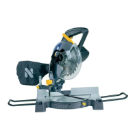
COMPONENTS AND CONTROLS (PIC.1)
Brush cover and motor housing
Blade guard release lever
COMPONENTS AND CONTROLS (PIC.1)
Handle c/w motor and On/Off switch
Laser battery compartment
When boxed or during storage and transportation the saw head
is locked in the down position.
Before carrying out any maintenance or adjustments the
machine must be disconnected from the mains power supply.
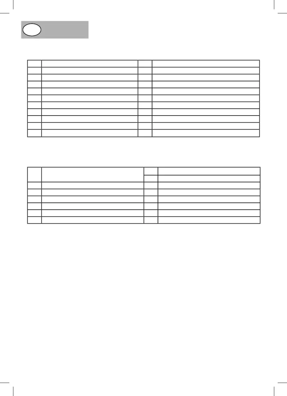
INSTALLING THE MITRE SAW (PIC.2)
This machine has four 12mm mounting holes in its base (Pic.2)
(2.1). These can be used to perma nently secure the saw to a
workbench with suitable screws or bolts. Alternatively, if the
machine needs to be moved frequently it can be secured to a
base of 19mm plywood to provide a more stable base.
With exception of the dust collection bag and the table locking
knob, this machine comes fully assembled.
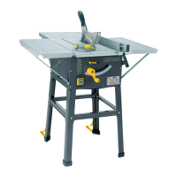
FITTING THE TABLE LOCKING KNOB (PIC.3)
To fit the table locking knob locate the threaded hole in the front
of the table and screw in the table locking knob (Pic.3) (3.1) .
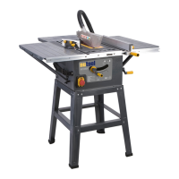
FITTING THE DUST COLLECTION BAG (PIC.4)
Fit the dust bag over the extraction outlet situated at the rear
of the machine (Pic.4) (4.1). The outlet has a hinged flap which
deflects the saw dust downwards when the dust bag is not used.
The flap is shown in the up position to allow the dust bag to
be attached (Pic.4) (4.2). The dust collection bag should be
emptied frequently as a full bag reduces its effectiveness to
Caution: Dust particles may cause respiratory problems
especially those from MDF board. For protection it is
recommended that an approved dust mask is worn.
Caution. When boxed or during storage and transportation the
saw head is locked in the down position. To release the head
ready for operation apply downward pressure to the handle
and pull out the lock pin (Pic.5) (5.1) and allow the head to rise
gently to its upper position.
ADJUSTMENTS REQUIRED BEFORE USING THE
The following adjustments must be made before operating the