MS51
Dec. 17, 2019 Page 261 of 316 Rev 1.01
MS51 SERIES TECHNICAL REFERENCE MANUAL
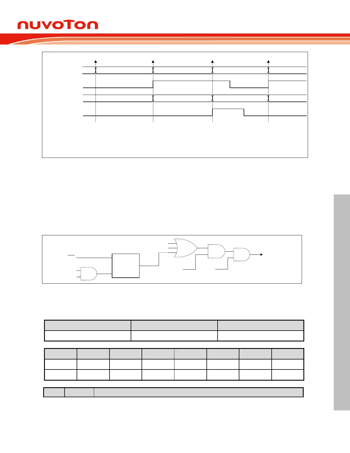
Shifting Data[n] in Shifting Data[n+1] in
SPIF
Data[n] Data[n]
Read Data Buffer
Shift Register
Shifting Data[n+2] in
SPIOVF
Data[n+2]
Data[n] Receiving Begins Data[n+1] Receiving Begins Data[n+2] Receiveing Begins
[1] When Data[n] is received, the SPIF will be set.
[2] If SPIF is not clear before Data[n+1] progress done, the SPIOVF will
be set. Data[n] will be kept in read data buffer but Data [n+1] will be lost.
[3] SPIF and SPIOVF must be cleared by software.
[4] When Data[n+2] is received, the SPIF will be set again.
[1]
[2]
[3]
[3]
[4]
Figure 6.9-7 SPI Overrun Waveform
6.9.7 SPI Interrupt
Three SPI status flags, SPIF, MODF, and SPIOVF, can generate an SPI event interrupt requests. All
of them locate in SPInSR. SPIF will be set after completion of data transfer with external device or a
new data have been received and copied to SPInDR. MODF becomes set to indicate a low level on
SS
causing the Mode Fault state. SPIOVF denotes a receiving overrun error. If SPI interrupt mask is
enabled via setting ESPI and EA is 1, CPU will executes the SPI interrupt service routine once any of
these three flags is set. User needs to check flags to determine what event caused the interrupt.
These three flags are software cleared.
SPIF
DISMODF
MSTR
ESPI
(EIE.6)
SPI Interrupt
SPIOVF
Mode
Fault
Detection
SS
MODF
EA
Figure 6.9-8 SPI Interrupt Request
6.9.8 Control Register
SPCR – Serial Peripheral Control Register