14 | nVent.com
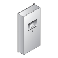
2.8.3 ETHERNET CONNECTIONS
The Ethernet port can be used to connect multiple NGC-UIT2 units to a host computer by
connecting to the user’s LAN system.
Bottom view
Ethernet
Network nod
Ethernet cable
NGC-UIT2-EX
Fig. 2.15 Ethernet connection (NGC-UIT2-EX)
2.9 TESTING THE NGC-30 SYSTEM
Once the wiring to the panel has been finished, confirm that it was done properly by completing
the following steps:
1. Turn the power on to all network devices (NGC-30-CRMs/-CRMSs and optional RMM2s &
PLI modules) and the NGC-UIT2.
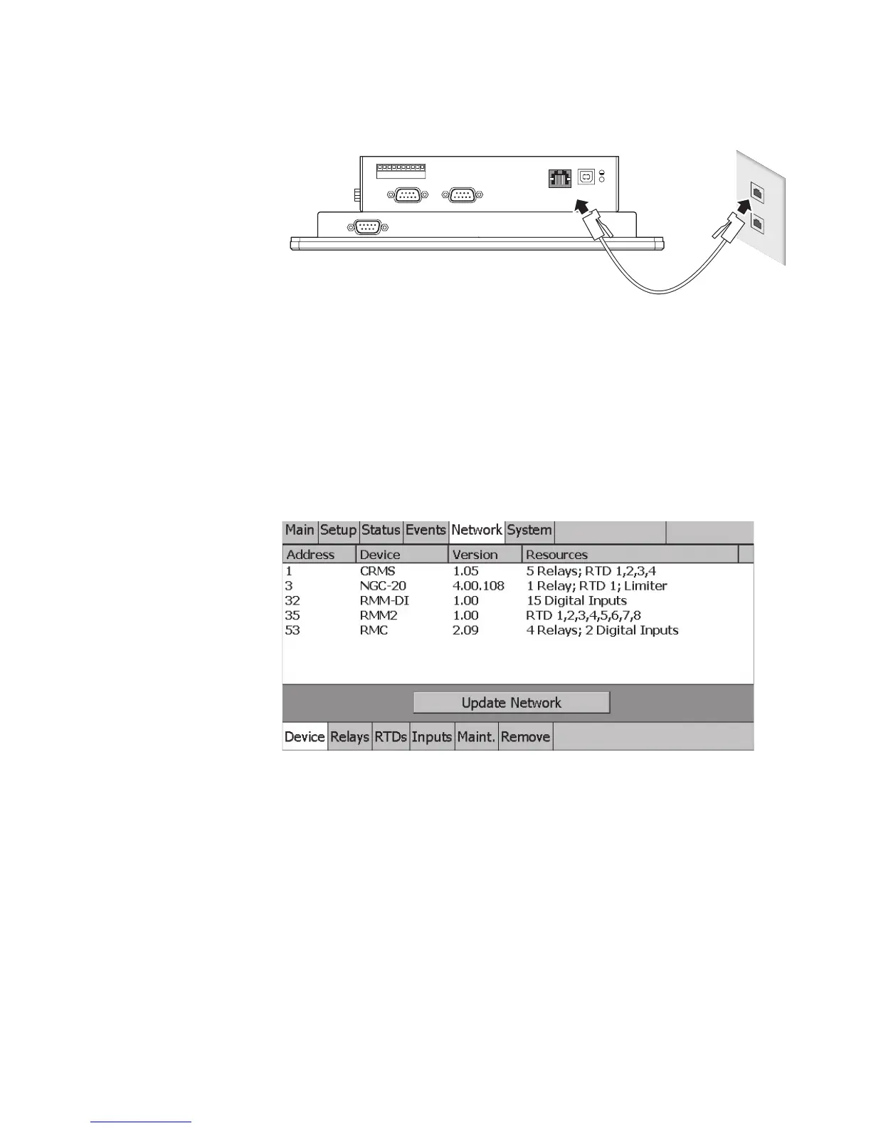
2. Once the NGC-UIT2 has booted up to the Main screen, Go to the Network | Device Screen
and press “Update Network.”
Fig. 2.16 Network|Devices screen
3. Confirm all modules have been scanned into the Network database.
4. If a device or an RTD is installed but does not show up in the Network | Devices Screen,
turn the power off to the system and:
For Devices:
a. Confirm the device has a unique address (refer to section 3.2 on page 24)
b. Confirm the device is being powered
c. Confirm the RS-485 connection is in place with the correct polarity (refer to section 2.6.5)
For RTDs:
a. Confirm the RTD connection is in place with the correct polarity
b. Perform a resistance check of the RTD. The resistance should be in a range of 70–250
ohms
Turn the power on to all devices (NGC-30-CRMs/-CRMSs and optional RMM2s & PLI) and the
NGC-UIT2. Once the NGC-UIT2 has booted up to the Main screen, Go to the Network | Device
Screen and press “Update Network.” Confirm all NGC-30-CRM s/ -CRMSs, RTDs, and/or RMM2s
and PLI modules have been scanned into the Network database.
 Loading...