16 | nVent.com
3.1.2 NGC-UIT2 LOCAL AND REMOTE NETWORK CONNECTIONS
The NGC-UIT2 communicates to both a local field network and optionally to a remote
monitoring and control network.
Local Field Network Connection
The local field network always uses an RS-485 serial connection running over shielded
twisted-pair cable. This network is used to connect the NGC-UIT2 to its control and monitoring
modules:
• RAYCHEM Mechanical Contactors Controller - NGC-30-CRM
• RAYCHEM Solid State Relay Controller - NGC-30-CRMS
• RAYCHEM Current Transformer Module Controller - NGC-30-CTM
• RAYCHEM Voltage Monitoring Module - NGC-30-CVM
• RAYCHEM Remote Monitoring Module for Temperature Measurement - RMM2
• RAYCHEM Remote Monitoring Module for Digital Inputs - RMM-DI
• RAYCHEM Power Line Carrier Interface Module - PLI
The local field network must follow configuration rules about topology and termination of
network end devices.
Remote Monitoring and Control Network Connection
The remote monitoring and control network communicates via a selectable network
connection port using either RS-485, RS-232, or 10/100Base-T Ethernet. This network is
used to connect to multiple NGC-UIT2 systems and communicate with a central PC running
RAYCHEM Supervisor software. The RAYCHEM Supervisor software provides centralized
status and alarm monitoring, data logging, and remote configuration control over all attached
NGC-UIT2 systems in the network. The remote monitoring and control network must also
follow configuration rules about topology and termination of the network end devices.
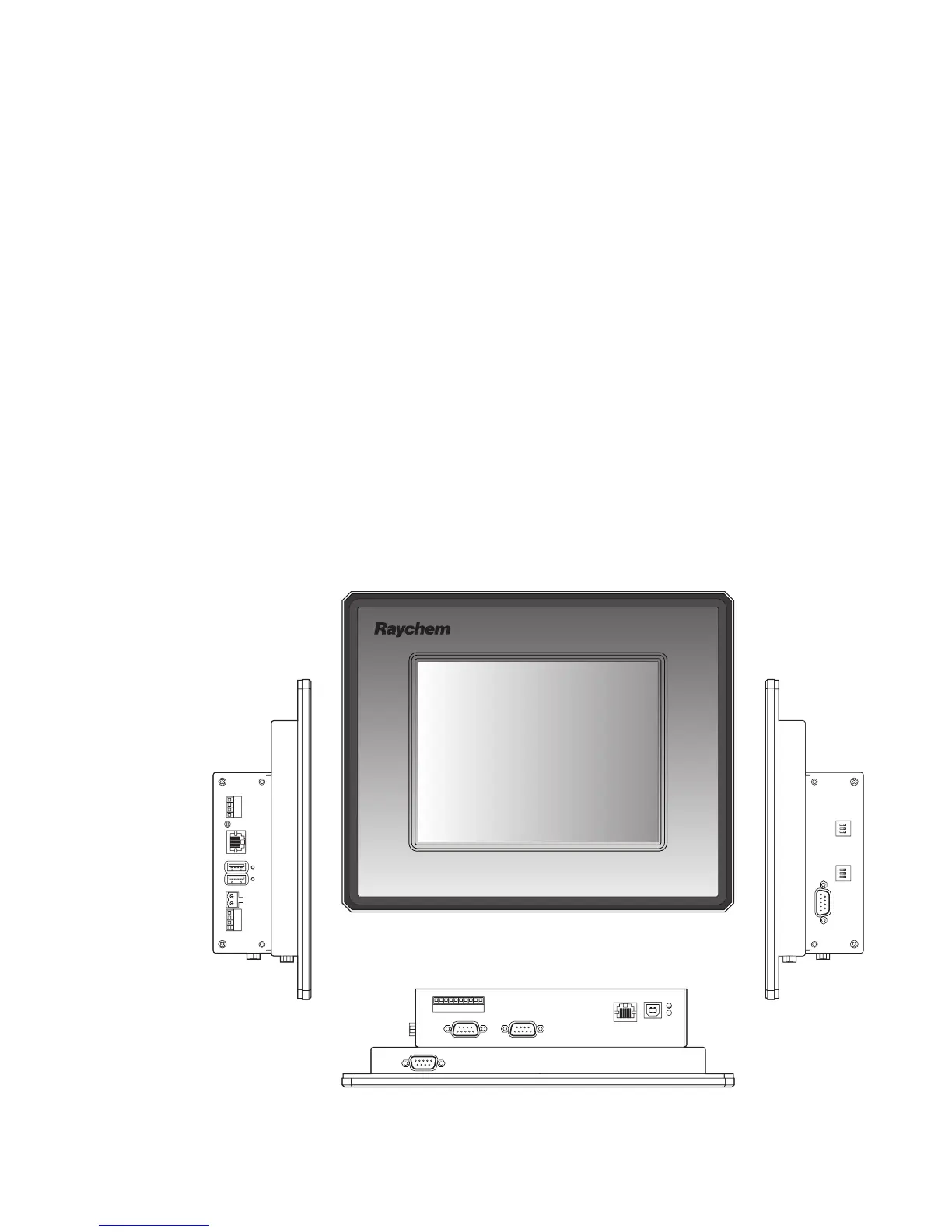
Front view
RS-485 2
Debug Port (not used)
Ethernet
USB device port
(not used)
Open Collector Outputs
RS-485 1
Side view
Side view
RS-232
RS-485-1
Termination
RS-485-2
Termination
USBPower
RS-485
(not used)
CAN
(not used)
RS-485
(not used)
Reset
Fig. 3.2 NGC-UIT2-EX touch-screen display, controls, and connections
 Loading...