8 | nVent.com
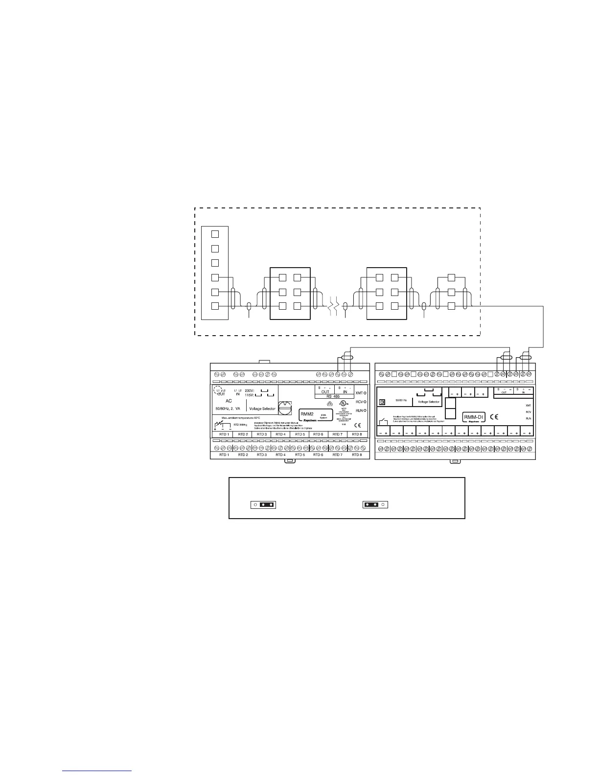
In order for the RS-485 network to work properly, you must enable the termination resistor for
the first and last device. The devices shown in gray in Fig. 2.5 represent the devices for which
you must enable the termination resistors. The devices that are not grayed out represent the
devices for which you should not enable the termination resistors.
Optional RMM2 Installed in the Field
Refer to the RMM2 Installation Instructions (H56848) for field installation instructions.
You must connect a RS-485 connection from the RMM2 to an open RS-485 connector on the
NGC-30-CRM/-CRMS board in the RAYCHEM NGC-30 panel. To make this connection, a
pre-wired terminal block has been provided in the RAYCHEM NGC-30 panel. Connect the
RS-485 wire from the RMM2 to TB (per the panel drawing) while maintaining the correct
polarity. If the RMM2 is the first or last device in the RS-485 network, connect the
J17 termination jumper to pins 1 and 2. If the RMM2 is not the first or last device in the
RS-485 network, connect the J17 termination jumper to pins 2 and 3.
0
Jumper
RMM2
NGC-30-CRM/-CRMS #1NGC-UIT2
RS-485
NGC-30-CRM/-CRMS #8
NGC-30 Panel
RS-485 RS-485
BK
WH
(–)
S
(+)
S
BK
TB*
WH
BK
TB*
3
WH
+
–
1
2
3
1
2
S
BK
TB*
WH
S
BK
TB*
3
WH
+
–
+
–
1
2
3
1
2
S
S
BK
WH
S
+
–
BK
WH
S
6
4
5
TB*
1
3
2
4
6
5
J17
123
Default position (for all RMM2
units in network except first or last one)
J17
123
Termination mode
(first or last RMM2/RMM-DI in network)
* Reference panel drawing for terminal block number
~
LN LN
Out
IN
1.5 VA
DI -1
DI-13 DI-14 DI-15
DI -2 DI -3 DI -4 DI -5 DI -6 DI -7 DI -8 DI -9 DI -10DI -11DI -12
DI Wiring: Output: min 12V @ 10mA
ADDR
H
ADDR
L
RS 485
230V:
115V:
Fig. 2.6 RMM2 RS-485 field wiring and termination jumper setting
 Loading...