4
Please reference Chamber Plans for more information
on installation.
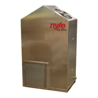
Step 1: Place the dehumidier at the center of the
long wall with the inlet lter facing the board pile.
Step 2: Connect an appropriate length drain hose.
The drain must have a trap.
The dehumidier can be elevated any reasonable
amount to help the drain gravity feed. If the drain
hose extends outside (not to a oor drain in the kiln)
the wall opening should be sealed around the hose.
Never have a oor drain.
Step 3: Place the controller at a convenient point
outside the chamber near the dehumidier.
Step 4: Remove the cover
Step 5: Drill holes in the kiln wall to allow control
cables and separately the sensor wires (inside the
controller) to be carefully routed into the chamber.
Do not route control and sensor wires through the
same hole.
Step 6: Mount the Dry Bulb Temperature Sensor 6 to
12 inches from the wall 4 feet o the oor, at least 3
ft from kiln unit, away from the blower outlet, for an
accurate reading.
Step 7: Remove the right side panel of the dehumidier
gaining access to the compressor and terminal strip.
Step 8: Securely connect the control cable to the
dehumidier.
Step 9: Carefully connect each wire to their
corresponding terminal. Do not stretch or over stress
the cable.
Wire insulation is marked with the corresponding
terminal number.
Step 10: Seal holes after wires are installed to keep
moisture from the control box. Seal the holes in the
kiln wall.
Step 11: Install the fans in locations over the lumber
see Chamber Plans as a reference.
Step 12: Install and caulk the vents so that they are
on opposite sides of the fans and at opposite ends of
the kiln.
The vents should be located as shown on the
chamber drawings.
Step 13: With the system switch in OFF position, plug
in the power cable (the special receptacle for the L53
is supplied by Nyle).
Equipment Installation


 To Next Page