NZXT. 6
2. Connect the power switch pin (labeled POWER SW) to the
PWR connector on the motherboard. (Yellow/White +/-)
3. Connect the HDD LED (labeled H.D.D LED) to the
appropriate headers on your motherboard. The HDD LED
located on the front panel should flash green when there is
activity in the hard drive. (Green/White, +/-)
4. Connect the four pin Molex leading from the front panel to
activate the single blue LED stripe on the aluminum panel.
All White and Black Pin Connectors correspond to ground.
USB Installation
1. The USB is located of the top on your front panel.
2. Refer to your motherboard manual and match the labels on
the USB port connectors with your motherboard in order to
install.
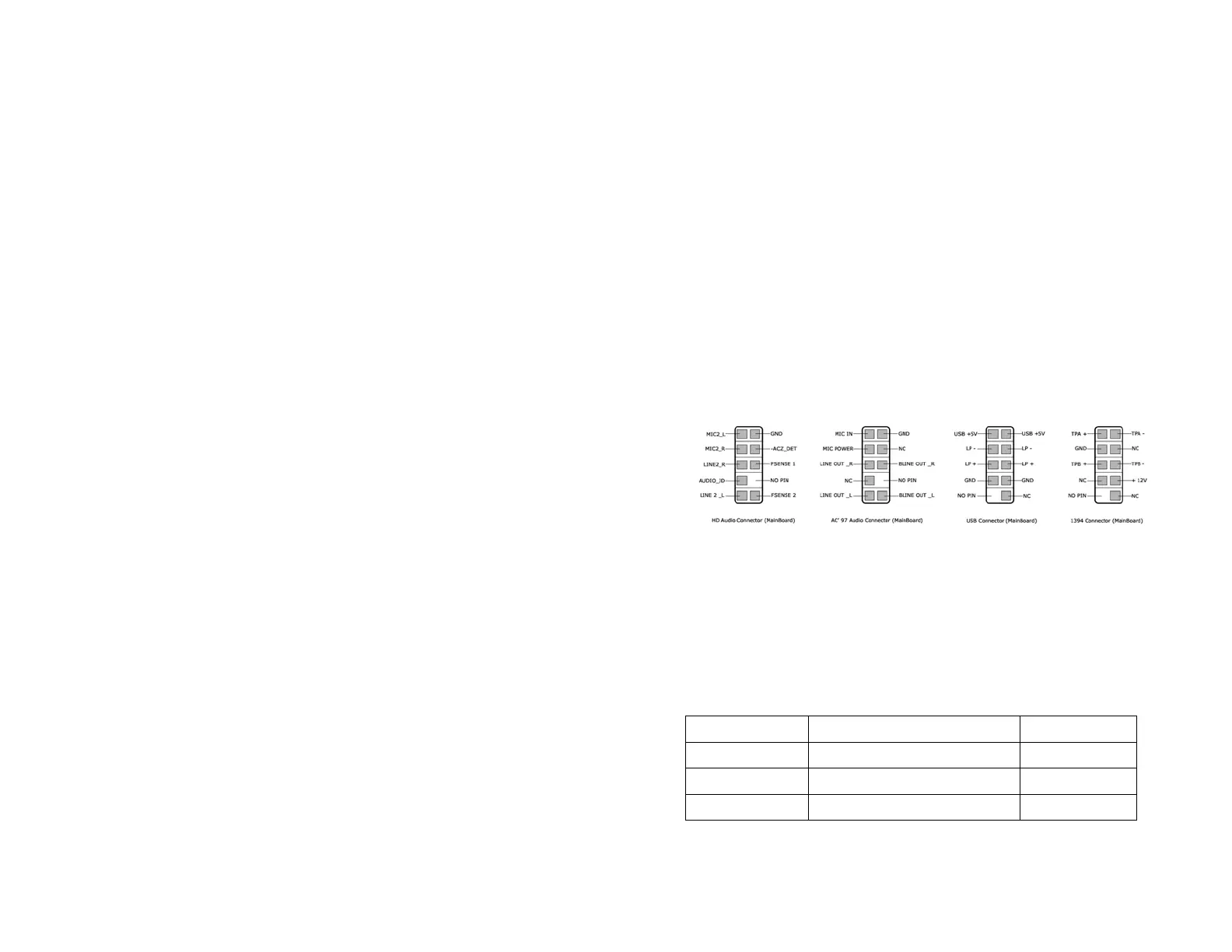
Audio Port Installation
1. Please first refer to your motherboard manual and match the
labels on the audio wires with your motherboard pins.
2. The green input is the speaker input and the pink input is the
microphone input.
Case Pins Signal Description ASUS© Pins
MIC-IN Front Microphone input Signal MIC2
MIC-POWER Front Microphone Power MICPWR
GROUND Front Audio Ground AGND
L-OUT Front Left Channel Audio Signal Line out_L
 Loading...