12x7-9 13x6-8
Use a tank designed for gasoline. (Tanks designed
for glow fuel use a rubber cap which is deteriorated
by gasoline.)
A 160cc tank will provide 12 to 13 minutes flight.(With
full throttle, it will provide 8 to 10 minutes flight.)
Install a commercially available gasoline fuel filter
between fuel tank and carburetor. (Clean the filter
from time to time.)
FUEL TANK & LINES
CARBURETOR PARTS NAME
PROPELLER
The choice of propeller depends on the design and
weight of the aircraft and on the type of flying in which you
will be engaged. Determine the best size and type after
practical experimentation. As s starting point, refer to the
props listed in the table shown below. Slightly larger, or
even slightly smaller props than those shown in the table
may be used, but remember that propeller noise will
increase if blade tip velocity is raised due to high rpm or if
a larger diameter/lower pitch prop is used. Be well aware
that the propeller rotating arc will increase when using a
larger propeller with this engine. Carry out the needle
adjustments only after stopping the engine. Do not allow
your face or hands to come close to the rotating prop.
Type
Size (DxP)
Sport/Acro/Scale
Warning:
Make sure that the propeller is well balanced.
An unbalanced propeller and/or spinner can cause
serious vibration which may weaken parts of the
airframe or affect the safety of the radio-control system.
Do not use any propeller which has become split,
cracked or nicked even very slightly, or received
strong impact even if no apparent damage is visible.
Since the GGT10 is intended to be started with an
electric starter, the addition of a spinner assembly for
centering the starter sleeve is desirable.
Special propeller locknut sets are available for use
with spinners. Use a good quality well balanced
spinner, enclosing the propeller boss.
Make sure that it is of precision-made and sturdy
construction so that the spinner shell cannot loosen
when the starter is used.
Make sure the spinner notches do not interfere the
propeller. If they do, cut the notches to clear.
MIXING OF OIL
Use regular gasoline. (No need to use high octane
gasoline.)
Alcohol based glow fuel cannot be used in this
engine. Not only will the engine not work properly
but the internal carburetor plastic parts will be
damaged.
Use high quality commercially available 2 stroke
engine oil.
Follow the oil manufacturer’s recommendations
concerning the mixture ratio of gasoline and oil.
If there is no recommendation, mix with a 25~30:1.
We have checked the following oils with the
mixture of 50:1.
KLOTZ ModeLube®
AMSOIL Saber
Zenoah Genuine FC Class
Concerning the mixture ratio for running-in, follow
the instructions in the RUNNING-IN section.
Regulator
It is recommended to seal the fitting faces of engine
exhaust and silencer with liquid gasket. Gasket at the
joint part of the silencer will lose its sealing effect in a
long time running. In this case, replace the gasket or
apply liquid gasket to the joint.
Use fuel line keepers of stainless wire, etc. at the end
of the tubing to prevent the tubing from coming off.
This engine does not require a muffler pressurized
fuel system but be sure to provide an air vent.
Be sure to use a gasoline
resistant fuel tank cap.
Be sure to equip
air vent pipe.
Be sure to use fuel line keepers of
stainless wire, etc. to prevent tubing
from coming off.
Be sure to replace tubing
inside periodically.
To the fuel
pump inlet
tubing for
re-fuelling
Be sure to install an in-line fuel filter between the
tank and carburetor to prevent foreign matter in the
tank from entering the carburetor. Clean the filter
periodically.
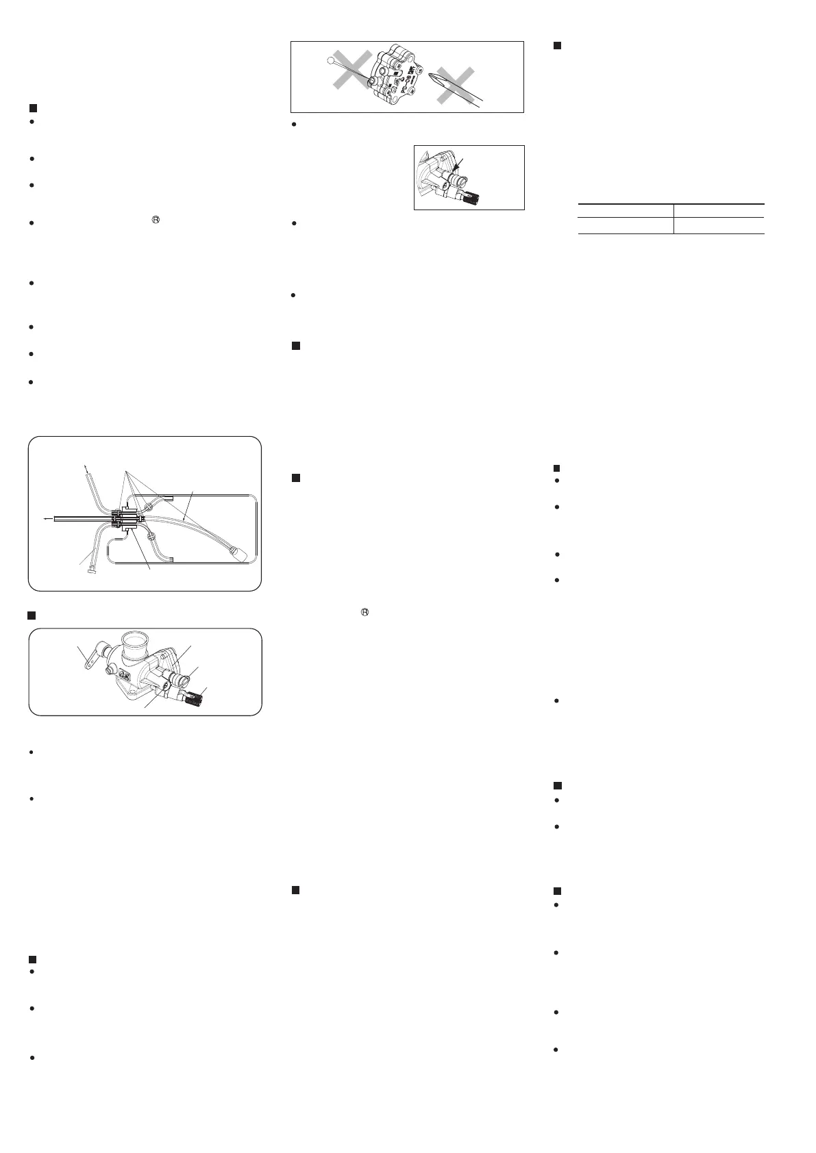
Needle Valve
Mixture Control Valve
Throttle Lever
Fuel Inlet
NEVER disassemble the fuel pump or pressure
regulator. Their original performance may not be
restored after reassembly.
DO NOT allow foreign matter to enter the fuel
system. Dirt inside the pump or regulator, no matter
how small, may obstruct the flow of fuel and prevent
these components from working properly.
CARE OF FUEL PUMP & REGULATOR
DO NOT obstruct the small rectangular hole at the
bottom of the regulator, nor the regulator will not
function correctly.
NEVER insert anything into the inlet or outlet nipples
in an attempt to clear a suspected obstruction.
ALWAYS use fuel filters. Keep the fuel tank
scrupulously clean and filter all fuel as it enters the
tank (e.g.via an O.S.'Super-Filter' Code No.72403050)
and use a good quality in-line filter between the tank
and pump. Remember to inspect filter screens at
regular intervals and rinse clean as necessary.
Rectangular
hole
NEVER use kerosene, thinner or any organic solvent
for cleansing the pump. Rubber parts will be ruined
by these materials. Use only alcohol (methanol) or
gasoline.
THROTTLE LINKAGE
Before connecting the throttle to its servo, make sure
that the throttle arm and linkage safely clear any
adjacent part of the airframe structure, etc., as the
throttle is opened and closed. Connect the linkage so
that the throttle is fully closed when the transmitter
throttle stick and its trim lever are at their lowest
settings and fully open when the throttle stick is in its
fully-open position. Carefully align the appropriate holes
in the throttle arm and servo horn so that they move
symmetrically and smoothly through their full travel.
For plumbing use TYGON F-4040A (Yellow color)
or strong nitrile rubber of more than 2.4-3.2mm ID
and 4.8-6.4mm OD. Replace tubing periodically as it
becomes hardened. (Replace tubing inside the fuel
tank every six months.)
The Needle-Valve
For adjusting the mixture strength when the throttle is
fully open Needle-valve adjustment effect the mixture
strength at round mid speed.
The Mixture Control Valve
For adjusting the mixture strength at part-throttle and
idle speed, to obtain steady idling and smooth
acceleration to mid speed.
Two adjustable controls are provided on this
carburetor.
Please note with this carburetor, needle-valve
adjustment does not effect the mixture control valve
adjustment but the mixture control valve adjustment
effects the needle-valve adjustment. Therefore, it is
required to adjust also the needle-valve when the
mixture control valve is adjusted. Mixture control valve
is pre-set at the near-best position when the engine
leaves the factory. Therefore, it is not necessary to
adjust the mixture control valve until running-in is
completed.
Use a fuel with increased oil content and set the
needle a little on the rich side. Too rich a needle
setting may cause misfiring or erratic running due to
fouling of the plug.
Use a 25:1 fuel/oil mixture if the particular brand of
oil states 50:1 mix. Use a 20:1 fuel/oil mixture if the
particular brand of oil states 25:1 mix.
Set only the high speed needle 200 below maximum
rpm. The low speed needle need not be richened.
No need to carry out running-in on a bench nor with
the model fixed. Just fly the model with the above
mentioned fuel and needle setting.
A total of 10 flights (2 litters fuel) are required.
Avoid prolonged full throttle running at initial stage,
and gradually extend the full throttle running time.
RUNNING-IN
GLOWPLUG IGNITER
For the plumbing in the fuel tank, we recommend
using O.S. fluororubber tube 2 mm ID x 4 mm OD x
500 mm length (code # 28382100).
A glow plug heater for GGT10 is nothing special.
You can use a conventional glow plug igniter.
You may find the G5 glow plug filament does not
glow as bright as the conventional glow plugs.
But you can start the engine without difficulties since
the flashpoint of gasoline is lower than that of
alcohol based glow fuel.
With a gasoline engine, passages in the carburetor
are narrower than that of a glow engine, and
therefore very sensitive against foreign matter such
as dust. It is suggested to use optional accessory
Super Filter L (Code No. 72403050) when filling a
tank in the model from a container used for
transportation or storing.
FUEL TUBE BUBBLES
Heat transferred to the PD-08 pump during engine
operation may create bubbles in the fuel tubing
between the pump and carburetor. The bubbles will
prevent the engine from performing properly. Even
if the air temperature is relatively low, heat can be
transferred to the pump due to your cowling
design. If this happens, you can correct it by (1)
cutting a vent in the cowling that allows cool air to
pass through, or (2) relocating the pump inside the
firewall or outside the cowling.
HOW TO RELOCATE THE PD-08 PUMP
1. Remove the pump.
Unscrew the M3x28 fixing screws (2 pcs). Take out
the pump.
2. Remove the pulse tube.
Disconnect the short yellow pulse tube that
connects the engine cover plate to the pump.
You’ll see a pulse spacer inside the short tube.
Take it out, set it aside and do not lose it.
3. Extend the pulse tube.
Use TYGON F-4040A (yellow) or strong nitrile
rubber of at least 2.4 to 3.2mm ID and 4.8 to 6.4mm
OD. To avoid engine malfunction, the maximum
length of the tube should not exceed 150mm. You
may not need to use the pulse tube spacer if the
tube is much longer than the factory setting.
Otherwise, insert the spacer (which regulates pulse
pressure to the pump) into the tube.
Use stainless wire keepers at the end of the tubing
to prevent it from coming off. The tubing will harden
over time, so replace it periodically.
4. Attach the pump.
If you attach the pump on a frame or cowling, the
existing M3 x 28 screws might not be long enough.
You may need extra M3 screws and nuts.
You can also choose not to attach the pump in the
fuselage. In this case, wrap it with foam or sponge
so it will not move around. Also be sure to bind the
pump itself tightly with the existing screws and M3
nuts (the nuts are included as standard accessories).
If you don’t, fuel may leak from the pump.
 Loading...