Do you have a question about the O.S. engine GF40U-FI and is the answer not in the manual?
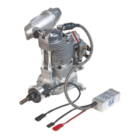
Details about the IG-08A igniter model, including power supply and connection.
Information on the NGK CM-6 spark plug, installation, and recommended tightening torque.
Description of inline fuel filter usage and non-bubble weight for fuel tanks to prevent air bubbles.
Guidance on using hose clamps to fix pressurized tubes to joints, recommending specific tubing materials.
Purpose of connector locks for sensors and igniter power to prevent accidental disconnection.
Details on a special tool for attaching/detaching temperature sensors like intake air and cylinder head.
Use of a converter for UART serial signal from ECU to RS-232C for computer connection.
Information regarding the power supply cord specifications, voltage range, and current limits.
Details of Wiring harness A, connecting sensors and communication devices to the ECU.
Details of Wiring harness B, connecting drive components like fuel pump and injector to the ECU.
Description of the extendable pump connection cord for fuel system components.
Connection details for the crankshaft rotation sensor to the ECU, specifying signal and ground.
Information on the CAN communication connector, its pins, and signal types for the ECU.
Specifies the power supply requirements, voltage range, and connection for the ECU.
Details the connection for the fuel pump to the ECU, including voltage and ground.
Connection instructions for the throttle servo to the ECU, detailing signal, power, and ground.
Details the connection for the injector harness to the ECU, specifying voltage and ground.
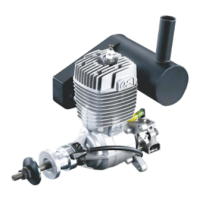
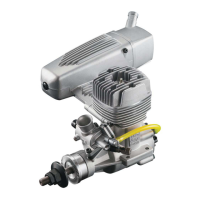
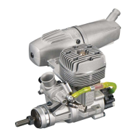
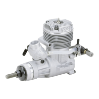
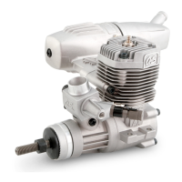
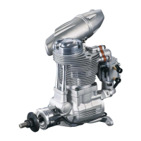
| Cooling System | Air-cooled |
|---|---|
| Type | 4-stroke |
| Fuel Type | Gasoline |
| Recommended Propeller Sizes | 11x6, 12x6 |
| Ignition | Electronic ignition |
| Lubrication | Oil mixed with fuel |