Do you have a question about the O.S. engine PEGASUS 320 and is the answer not in the manual?
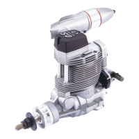
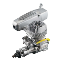
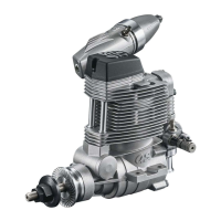
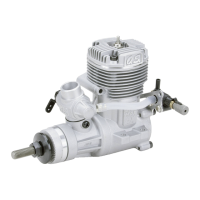
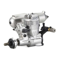
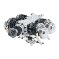
The O.S. ENGINE FF-320 Pegasus 320 is a horizontally-opposed, four-cylinder, overhead-valve, four-stroke engine designed for model aircraft. This engine is known for its smooth running characteristics and reliable performance.
The FF-320 Pegasus 320 is an internal combustion engine that powers model aircraft. Its four-stroke design means it completes a power cycle in four piston strokes (intake, compression, power, exhaust), offering efficient fuel consumption and smoother operation compared to two-stroke engines. The horizontally-opposed cylinder configuration helps to minimize vibration, contributing to stable flight and reduced stress on the airframe. The engine is designed to run on a mixture of methanol, castor oil (or a quality synthetic lubricant), and nitromethane for improved flexibility and power.
Starting the Engine: Before starting, ensure the throttle is fully closed and the propeller is turned counter-clockwise three revolutions. Open the needle-valve to approximately 40° open from maximum r.p.m. setting. For the first start, or after a long period of inactivity, prime the engine by turning the propeller counter-clockwise until fuel is drawn into the cylinders. Use an electric starter for easier ignition. Once the engine starts, gradually close the throttle and adjust the needle-valve for optimal performance. The engine should run at a stable idle speed for 5 seconds before attempting flight.
Running-In (Breaking-In): Proper running-in is crucial for engine longevity. For the first 10 minutes, run the engine at 500-1,000r.p.m. lower than maximum r.p.m. setting. This allows the internal components to wear in smoothly. Gradually increase the engine temperature to the maximum r.p.m. setting over approximately 10 minutes of running time. During the running-in period, avoid sudden throttle changes and prolonged idling.
Throttle Adjustment: The throttle valve operating lever can be located right or left by reversing the hexagon nut and cap screw. The throttle linkage should be adjusted so that the engine stops when the throttle stick and trim lever on the transmitter are fully retarded. This ensures the engine stops by cutting off the fuel supply. The needle-valve setting is critical for optimal performance and should be adjusted to achieve the best possible r.p.m. without the engine hesitating or stopping.
Propeller Selection: The choice of propeller depends on the design and weight of the aircraft and the type of flying in which you will be engaged. Determine the best size and type after practical experimentation. A larger diameter/lower-pitch prop will generally result in higher rpm than a smaller, higher-pitch prop. Always ensure the propeller is balanced to prevent excessive vibration. Use the O.S. Safety Locknut Assembly to secure the propeller.
Glowplugs: The FF-320 is designed for O.S. four-stroke glowplugs. A glowplug with a strong cast aluminum radial-type hood is used to be bolted securely to the firewall (front bulkhead) of the aircraft. Glowplugs are essential for starting and maintaining combustion. They should be checked regularly and replaced if damaged or worn.
Safety Instructions and Warnings: Always operate the engine in a well-ventilated area, as exhaust fumes contain carbon monoxide. Never touch the rotating propeller or any hot engine parts while the engine is running or immediately after stopping. Keep hands, face, and loose clothing away from the propeller. Fuel is poisonous and flammable; store it in a clearly marked container and out of the reach of children. Always wear safety glasses when operating the engine.
Valve Clearance Adjustment: Regular valve clearance checks are essential for optimal engine performance. The standard valve clearance, on both inlet and exhaust valves, is between 0.04mm and 0.1mm (0.0016-0.004 inch). Use a feeler gauge to check clearances. If the gap is found to be less than 0.04mm, it is not necessary to readjust the clearance. If the gap exceeds 0.1mm, it is advisable to adjust. Loosen the locknut on the rocker-arm, adjust the screw, and re-tighten the locknut while holding the adjusting screw stationary. Excessive valve clearance will cause loss of power, due to valves not opening sufficiently.
Carburetor Cleanliness: It is recommended that the fuel is passed through a filter when the tank is filled and that a good in-line filter is installed between the fuel tank and carburetor. Periodically remove the needle-valve holder from the carburetor and clean out the fuel passages.
Lubrication: The engine is lubricated by the oil mixed in the fuel. After each flying session, clean the crankcase to remove any accumulated oil and carbon residue. This helps prevent corrosion and ensures smooth operation. Apply a corrosion-inhibiting oil to all working parts if the engine is to be stored for an extended period.
Exhaust Pipe Adjustment: The direction of the exhaust pipe may be altered in accordance with individual installation requirements. The angle can be easily adjusted by loosening the nut that secures the exhaust pipe to the cylinder head. Use the 12mm wrench supplied.
General Maintenance: Regularly check all screws and nuts for tightness. Ensure all fuel lines are securely connected and free from leaks. Periodically inspect the engine for any signs of damage or wear. If any parts are damaged, replace them with genuine O.S. ENGINE parts. Do not attempt to modify the engine, as this can lead to malfunction and void the warranty.
| Brand | O.S. engine |
|---|---|
| Model | PEGASUS 320 |
| Category | Engine |
| Language | English |