Do you have a question about the Oberheim OB-8 and is the answer not in the manual?
Microprocessor adjusts volts per octave by sampling frequencies for each oscillator.
LFOs generated in software via DAC, eliminating hardware components for destination and amplitude.
Microprocessor scans pitch bend and vibrato levers, calculating voltage for pitch bending and vibrato.
OB-8 uses one CEM3320 per voice, electronically switched for 2-pole or 4-pole filter slopes.
Software calibration corrects op amp offsets by outputting compensating voltage to sample and holds.
Technicians' calibration instructions using microprocessor assistance and test LEDs.
Procedure to calibrate DAC offset and scaling using a voltmeter and test points.
Calibrates Bend Box trimmers to center the Pitch Bend and Modulation Levers.
Calibrates filter sustain and output volume offsets for matched voice board volumes.
Calibrates volts per octave for each oscillator using test LEDs and keyboard selection.
Tests all LEDs on the front panel and Bend Box except the Cassette LED.
Tests front panel switches by lighting their respective LEDs when pressed.
Calibrates filter resonance, volts per octave, and initial frequency for each voice.
Adjusts final volume trimmers on each Voice Board to ensure even volume between boards.
Detailed circuit diagrams for the OB-8 processor board.
Circuit diagrams for the OB-8 bend board.
Circuit diagrams for the OB-8 voice board.
Visual representation of component placement on the OB-8 voice board.
Visual representation of component placement on the OB-8 processor board.
Component layout for the first OB-8 potentiometer board.
Component layout for the second OB-8 potentiometer board.
| Type | Analog |
|---|---|
| Polyphony | 8 voices |
| Waveforms | Sawtooth, Square, Pulse, Triangle |
| LFO | 1 LFO with multiple waveforms |
| Envelopes | 2 ADSR envelopes |
| Memory | 120 patches |
| Control | MIDI (optional) |
| Year Released | 1983 |
| Oscillators | 2 per voice (VCOs) |
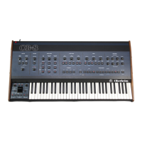
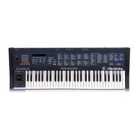
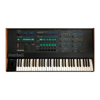
| Keyboard | 61 keys |
| Filter | 2-pole/4-pole switchable resonant low-pass filter |