File: UT-5601 Copyright © - OBL Metering pumps - All rights reserved
6.2 Signal connection
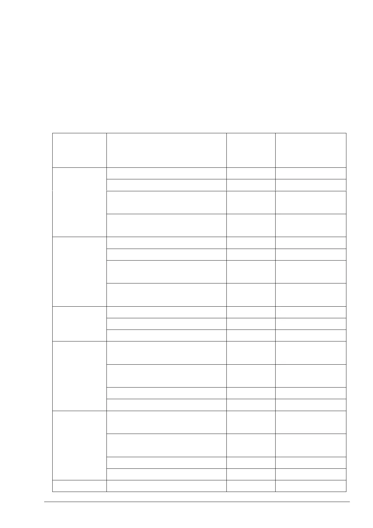
The KIT PRO has different signal connections, whose name are shown on the enclosure.
The KIT includes the relative connectors, which are provided with a 1-meter cable. The cables
supplied feature 4 conductors featuring different colours. The function of the input cables changes
depending on the hardware version. Please check the hardware operating on the controller in the
menu settings→firmware info→version. The version of the hardware can be 0.1 or 0.2 (from the
end of 2020). Table below Error! Reference source not found.shows the connectors needed.
Table 2 Connectors
KIT-PRO UL
CONDUCTOR
COLOUR
Remote Start/Stop (contact)
Ground (-)
(common for all pins of input connector)
4-20 mA/0-10V analogue (+)
(passive signal: power supply needed)
4-20 mA/0-10V/pulse (-)
(passive signal: power supply needed)
4-20 mA/0-10V/pulse (+)
(passive signal: power supply needed)
4-20 mA analog (+)
(passive signal: power supply needed)
4-20 mA analog (-)
(passive signal: power supply needed)
4-20 mA analog (+)
(active signal: no power supply needed)
4-20 mA analog (-)
(active signal: no power supply needed)