REGULATORS
DXI INTEGRATED FIRST STAGE
© 2002 Design 2000
OCEANICOCEANIC
OCEANICOCEANIC
OCEANIC®
Product Service Guide Product Service Guide
Product Service Guide Product Service Guide
Product Service Guide
Doc. 12-2205-r01 (01/00)
PG-6
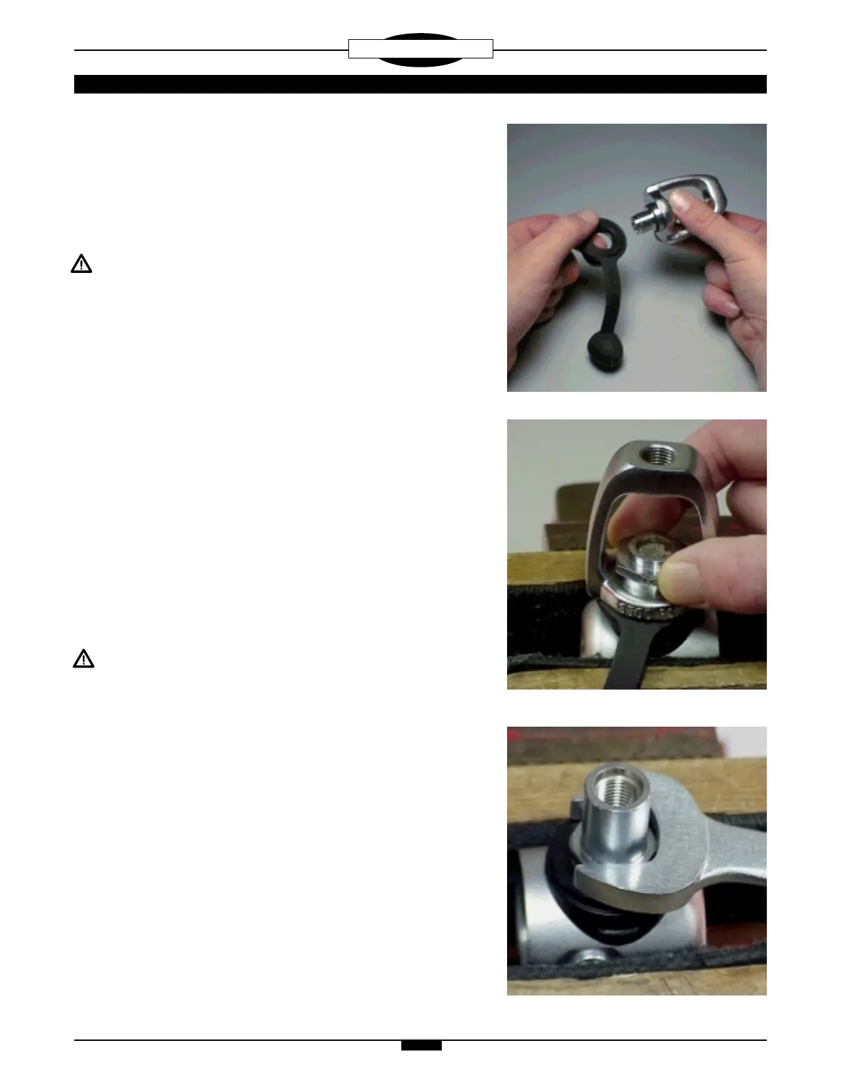
D. Insert the threaded end of the yoke retainer(6) through the
yoke(2), facing opposite the end which holds the knob assembly(1).
Place the protector cap(8) and the saddle(17) onto the yoke
retainer(6), with the flat side mating to the base of the yoke.(Fig. 13)
E. Secure the first stage body in a soft jawed or well padded vise,
with the threaded HP inlet bore facing straight up.
CAUTION: Tighten the vise only as needed to hold the first
stage secure, and DO NOT overtighten. Doing so will result in
permanent damage, rendering it inoperable.
F. Holding the yoke retainer, yoke, dust cap, and saddle together
between thumb and forefinger, mate the yoke retainer into the main
body, so that the threads seat properly. Hand tighten in a clockwise
direction until secure. (Fig. 14) Using a thin-wall, or modified, 1"
crow's foot wrench that is properly seated over the entire hex portion
of the retainer, tighten to a torque of 16-18 ft-lbs.
G. Install the knob assembly(1) into the yoke(2).
1D. DIN connector reassembly:
A. Lubricate and install the DIN filter housing o-ring(16) into the
groove on the end of the DIN filter housing(15).
B. Insert the threaded end of the filter housing(15) through the flat
side of the saddle(17).
C. Secure the first stage body in a soft jawed or well padded vise,
with the threaded HP inlet bore facing straight up.
CAUTION: Tighten the vise only as needed to hold the first
stage secure, and DO NOT overtighten. Doing so will result in
permanent damage, rendering it inoperable.
D. Install the filter housing(15) into the main body(28) so that the
threads seat properly, and hand tighten in a clockwise direction until
secure. Using a thin-wall, or modified 13/16" crows foot wrench that
is properly seated over the entire seating surface of the filter
housing flange, tighten to a torque of 16-18 ft-lbs. (Fig. 15)
E. Lubricate and install the conical filter o-ring(14) into the filter
housing(15), at the base of the filter cavity. Install the conical
filter(13) into the filter housing.
F. Install the protector cap(8) and the coupler wheel(12) down over
the stem of the filter housing(15), with the threaded end facing up.
G. Lubricate and install the DIN face o-ring(9) and filter retainer o-
ring(11) onto the filter retainer(10).
Fig. 14
Fig. 13
Fig. 15
 Loading...