FOR CLARITY PARTS ARE
REMOVED FROM CYLINDER
1. Plug
2. Notch
3. Spring
4. Spring end
5. Plug with O-ring
NOTE: Turn spring only clockwise in
order to fit the spring end into the notch
of the plunger to avoid loosening the
plunger during spring installation. Do
not pre1oad the spring.
9. Then compress the spring and screw
the plug in.
NOTE: To avoid overstressed timing
chain, the plug must engage into threads
within the first full turn.
10. Remove locking tool and install all
other removed parts.
11. Finally, tighten the plug.
CAMSHAFT TIMING GEARS
Camshaft Timing Gear Removal
Remove the valve cover , refer to TOP
END sub section.
Turn crankshaft to TDC ignition of the
respective cylinder and lock magneto
flywheel, see CAMSHAFT TIMING in
this subsection.
Unscrew timing chain tensioner. Refer
to TIMING CHAIN TENSIONERS in
this subsection.
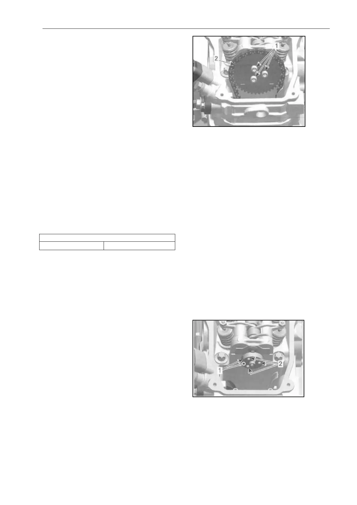
Remove camshaft timing gear retaining
screws.
1. Camshaft timing gear retaining
screws
2. Camshaft timing gear
NOTE: Secure timing chain with a piece
of wire.
Inspecting the Camshaft Timing Gear
Check camshaft timing gear for wear or
deterioration.
If gear is worn or damaged, replace it as
a set with
the timing chain.
For crankshaft gear, refer to BOTTOM
END subsection, see CRANKSHAFT.
Camshaft Timing Gear Installation
For installation, reverse the removal
procedure. Pay attention to the
following details.
1. Clean mating surface and threads of
camshaft prior installing camshaft
timing gear.
1. Mating surface on camshaft
2. Threads for camshaft screws
2. Crankshaft must be set to TDC
ignition position before installing the
timing chain, refer to CAMSHAFT
TIMING in this subsection.
3. Insta1l the camshaft timing tool on