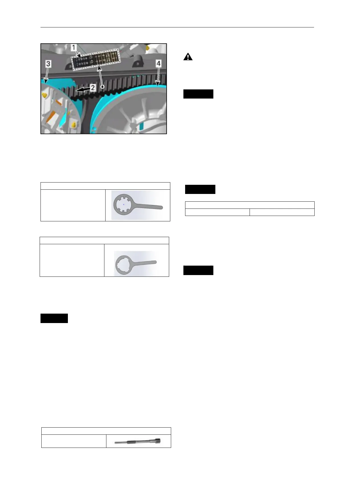
1.Arrow printed on belt
2.Rotation direction
3.Drive pulley (front)
4.Driven pulley (rear)
DRIVE PULLEY
Removing the Drive Pulley
1.Remove DRIVE BELT, see procedure
in this subsection.
2.Lock the drive pulley.
3.Loosen the drive pulley screw.
NOTICE Never use any type of impact
wrench for drive pulley removal.
NOTE: Do not unscrew the drive pulley
screw completely.
Remove service tool.
Apply axial pressure with your hand on
the gov-ernor cup until clutch puller for
removal is
in-stalled.
Remove drive pulley screw and spring
washer.
CAUTION Sliding sheave of drive
pulley is spring loaded.
Screw clutch puller in fixed sheave to
remove drive pulley.
NOTICE Use only recommended tool.
Disassembling the Drive Pulley
Drive Pulley
Screw clutch puller into fixed sheave
shaft about 63 mm (2-1/2 in).
Raise drive pulley by the sliding sheave
while knocking on the puller head to
disengage fixed sheave.
NOTICE Never tap on governor cup.
Lock the drive pulley as per removal
procedure.
Tighten drive pulley screw to specified
torque.
NOTICE Never use any type of impact
wrench for drive pulley installation.
DRIVEN PULLEY
Removing the Driven Pulley
1.Remove:
–
CVT cover
–
Drive belt.
2.Install the clutch holder.
Remove:
– Driven pulley screw (discard it)
– Collar washer.
4.Remove the clutch holder.
Pull the driven pulley out of the vehicle.
5.1If removed, reinstall the DRIVEN
PULLEY ADAPTER.