NOTE: With a fully charged battery and
noelectrical loads, specification is less than
10A.
If amperage or voltage is not within
specification, verify magneto and wires.
Replace:
– Voltage regulator if magneto test is
within specifications.
– Magneto if magneto test is not within
specifications.
VOLTAGE REGULATOR (RD)
Testing the Voltage Regulator Continuity
Due to internal circuitry, there is no static
test available
Voltage Regulator Wire Identification
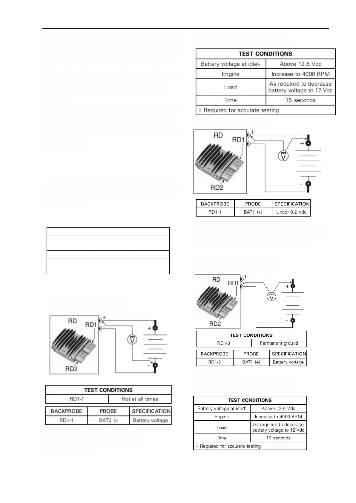
Testing the Voltage Regulator Power
1. Check voltage at RD1-1.
2. Connect a battery load tester.
3. Start vehicle.
4. Ensure proper test conditions
5.Measure voltage drop.
If voltage drop is above specification, locate
and repair damaged connector/wire.
Testing the Voltage Regulator Ground
1. Check ground at RD1-3.
2. Start vehicle.
3. Ensure proper test conditions.