Calibration
14. Check the Show Circular Mask box on the form and disconnect the laptop.
17. Insert a film envelope into the Beam Alignment Tool.
18. Expose the film in the following collimator iris positions (see the following diagrams):
• Normal field
• Mag1 field
• Mag2 field
• Minimum iris position
mm
10 0
2
34
1
50
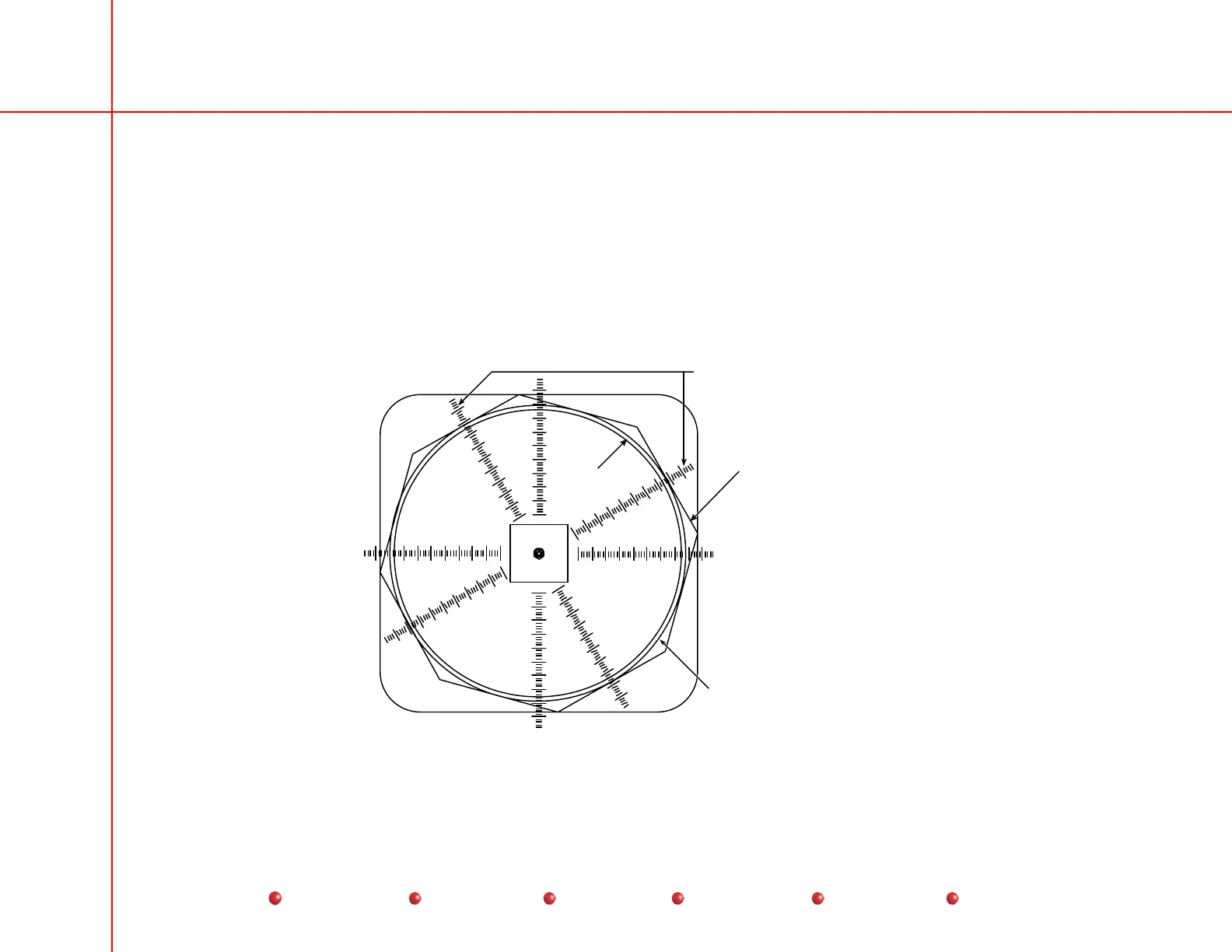
Use the ruler marks that intersect
the center of the flat portion of the
collimator iris leaves to determine
the X & Y film diameters.
Collimator Iris may only
be partially visible.
(1 or 2 leaves)
N orm al Fi eld Si ze
X-Ray beam produced by
the lead ring in the collimator
Circular
Blanking
Normal Field Size
58
Service
Periodic Maintenance
Contents
Schematics
Illustrated Parts
Installation