Overview
2-34
Service Periodic Maintenance
Contents
Schematics Illustrated PartsInstallation
External Interfaces
This paragraph discusses the External Interface PCB and Workstation rear panel. Refer to Section 9 - External
Interfaces for detailed circuit descriptions, troubleshooting information, and component replacement instructions.
External Interface PCB
The External Interface PCB connects via ribbon cable to the System Interface PCB, which connects to ISA slot 2 on
the Host Pentium CPU motherboard located in the Electronics box. As its name implies, the External Interface PCB
connects the motherboard to the outside world. It provides DC isolation where necessary and adapts system signals
to make them compatible with external equipment connected to the Workstation rear panel and Interconnect cable. In
some cases, the External Interface PCB passes signals straight through without modification. In other cases it adds a
simple pullup resistor or current-limiting resistor to a signal line. In other cases, the External Interface PCB uses an
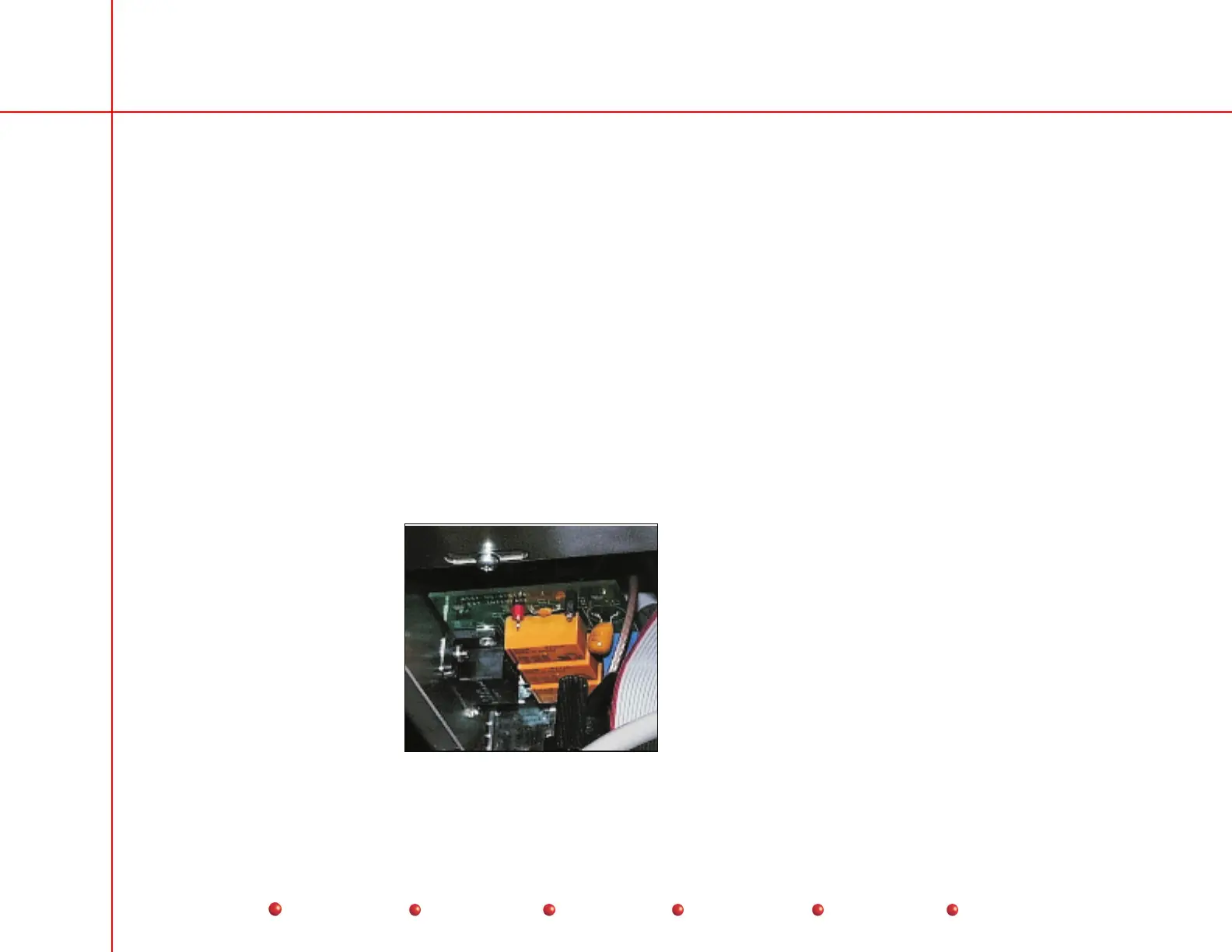
ISA bus signal to switch relay contacts. The External Interface PCB mounts directly behind the Workstation rear panel
as shown below.
View inside
electronics box
directly behind
rear panel connectors
External Interface PCB
 Loading...


