DC Power Distribution
The operating power for the Interlock system and the Image Intensifier power supply is further divided as shown in the next
diagram.
Power/Motor Relay PCB
See "Interlocks"
Section
24V_INTERLOCK
24V_IN
1
7
P7
K7
6
P5
1
P1
II
Power
Supply
15
J7
II_ON
(see "Image Intensifier
and Power Supply")
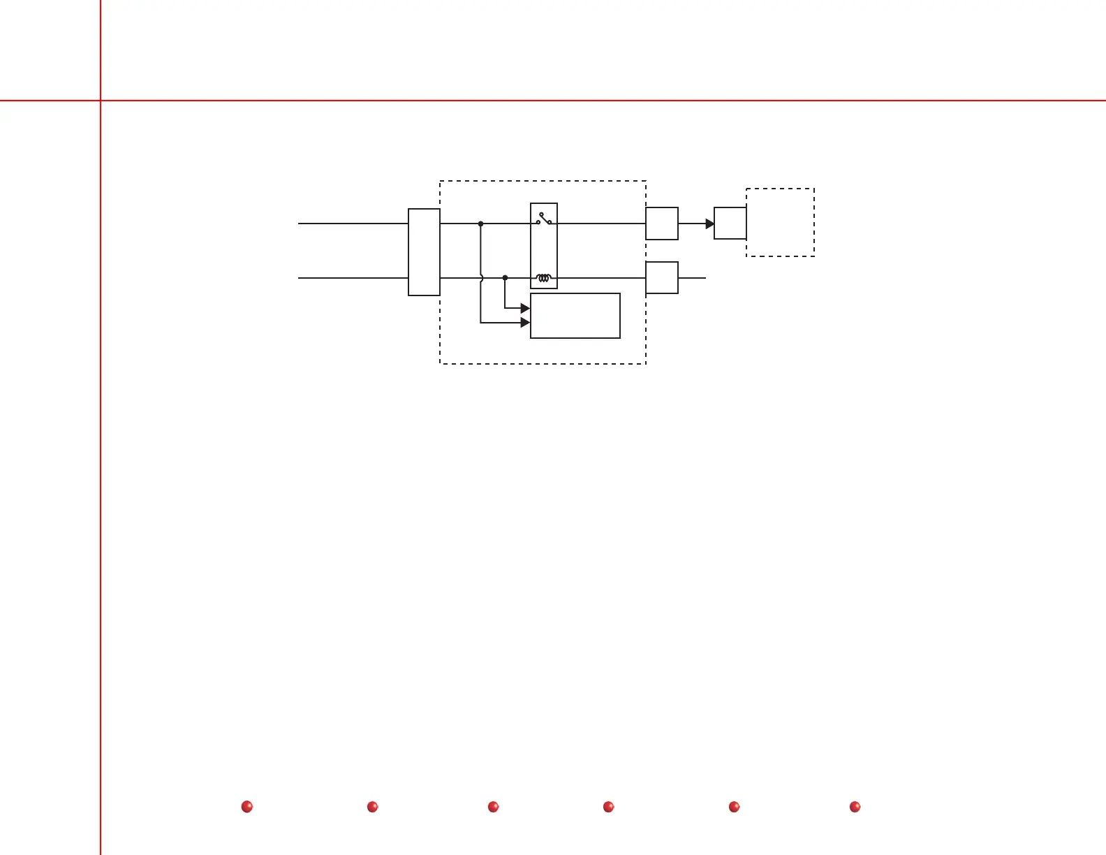
DC Operating Power for CCD Camera and Image Intensifier
In the Power/Signal Interface PCB, the +24VDC is divided into two separate circuits. The 24V_INTERLOCK does two things---
connects directly to the Interlock system, and also to the K7 relay coil, then to the Image Intensifier as II_ON. The II_ON becomes
a status signal monitored by the X-ray Controller PCB.
The 24V_IN goes into the Interlock system, and also to the K7 relay contact. Thus, with the PS2 +24VDC circuit energized, K7
controls power to the Image Intensifier power supply.
PS3 Output
Power Supply PS3 receives operating power as shown in the AC Power Distribution chapter of this manual. The PS3 output is
dedicated strictly to the vertical column. For details see the Vertical Column chapter of this manual.
10
Service
Periodic Maintenance
Contents
Schematics
Illustrated Parts
Installation
 Loading...


