Battery Charging
Circuit/Mechanical Descriptions
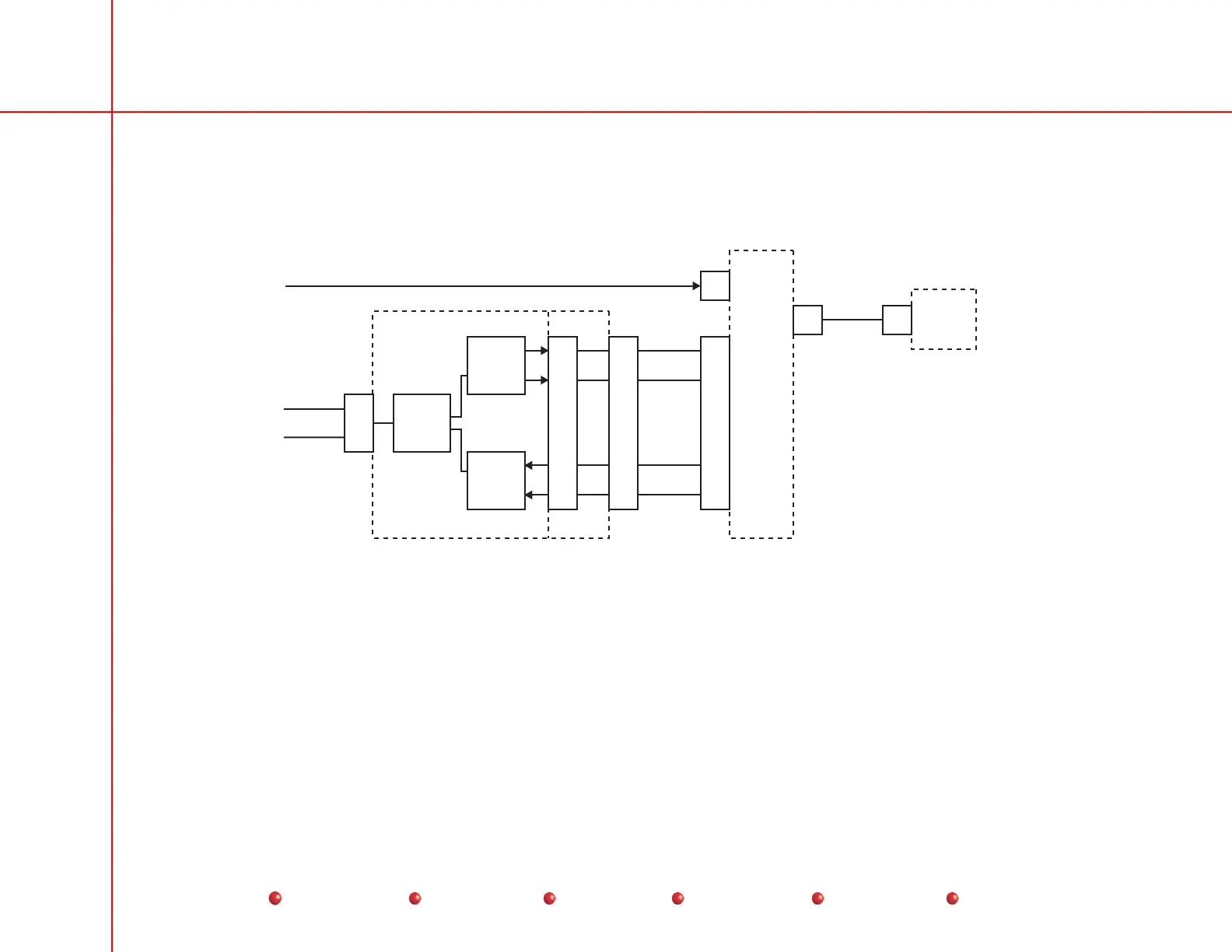
The battery charging circuitry is illustrated in the following diagram:
X-Ray Controller PCB
Battery
Charger
PCB
Battery
Charger
Capacitor/
Power
Module
ARCNET_HI
ARCNET_LO
Analog to
Digital
Conversion
486
Processor
Output
Latching
P5
17
18
P4
13
24
79
76
P2
1
4
6
2
A2J1
75
78
79
76
LINE_V_SEN
CHG_I_SEN
CHG_DISAB
HI_CHG_MOD
P1
4
P4
1
P3
1
CHRG_OUT
115VAC_PH_CH
(see AC Power Distribution)
Battery Charging Circuitry
When you turn on the Workstation, 115 VAC becomes available at the Battery Charger PCB, as previously explained in the AC
Power Distribution section of this manual. At the same time, DC power energizes the X-Ray Controller PCB, as described in the
DC Power Distribution section. With the X-Ray Controller PCB energized, signals exchanged between the two boards regulate
charger output according to battery charge and power demands of taking X-Ray shots. There are several LED indicators on the
Battery Charger PCB that indicate operation. For full information about them, you should refer to the Diagnostics chapter of this
manual.
2
Service
Periodic Maintenance
Contents
Schematics
Illustrated Parts
Installation
 Loading...


