OEC UroView
®
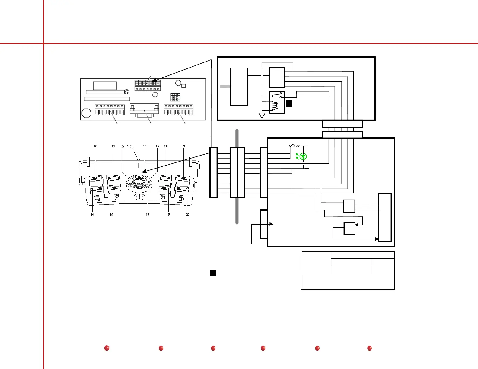
2800 Table/Generator Functional Block Diagrams
73
Service
Periodic Maintenance
Contents
Schematics
Illustrated Parts
Installation
Page 1 of 1
For Reference Only
07/01
28FTSWTC.DS4
2800
Table Footswitch
g
X1
Motron
Board
uP
X2
8VAC_1
8VAC_1
TAST_V-
8VAC_2
8VAC_2
V+
CLK_V-
DATA_V-
V-
P8 X8
UNDER
TABLE
F4 100mA
D9
DATA_IN
DATA_OUT
CLK
CLK_V-
DATA_V-
IC30
IC14
Footswitch
Board
1
2
3
4
5
6
7
8
9
1
2
3
4
5
6
7
8
9
1
2
3
4
5
6
7
8
9
9
3
6
7
8
2031
21
2
P2
TAST_V-
TABLE_V+
TABLE_CLK
TABLE_DAT
TABLE_V-
Table/Generator
Interface PCB
U49-51
Opto
U36
Decoder
ISA
K3
11- Tilt table down
12- Tilt table up
13- Store
14- Recall
15- Move tabletop to the left
16- Move tabletop to the right
17- Move tabletop to the head end
18- Move tabletop to the foot end
19- Lower tabletop
20- Raise tabletop
21- Move radiographic system to the head end
22- Move radiographic system to the foot end
+
_
Security
Lines
When activated by one of the security
lines, the TAST_V- signal enables the
table. See the Interlock diagram for
details.
1
1
X1
Power from
Table Power Supply
See System Power
Distribution Diagram
Page 5/5
X3
Table Footswitch