3
Operating Instructions and Parts Manual 24495
OSCILLATING TOOL
1/17
2017 OEMTOOLS
®
EXTENSION CORD SAFETY
WARNING
Keep the extension cord clear of the working area. Position the
cord so it will not get caught on the workpiece, tools or any other
obstructions while you are working with the power tool.
1. Make sure any extension cord used with this tool is in good condition.
When using an extension cord, be sure to use one of heavy enough
gauge to carry the current the tool will draw. An undersized cord will
cause a drop in line voltage resulting in loss of power and overheating.
2. The table below shows the correct size to use according to cord length
and nameplate ampere rating. If in doubt, use the next heavier gauge.
The smaller the gauge number the heavier the cord.
3. Be sure your extension cord is properly wired and in good
condition. Always replace a damaged extension cord or have it
repaired by a qualified electrician before using it. Protect your
extension cord from sharp objects, excessive heat and damp or
wet areas.
4. Use a separate electrical circuit for your power tools. This circuit
must not be less than 14 gauge wire and should be protected
with either a 15 A time delayed fuse or circuit breaker. Before
connecting the power tool to the power source, make sure the
switch is in the OFF position and the power source is the same as
indicated on the nameplate. Running at lower voltage will damage
the motor.
MINIMUM GAUGE (AWG) EXTENSION CORDS (120 V
use only)
Amperage rating Total length
More
than
Not
more
than
25'
(7.5 m)
50'
(15 m)
100'
(30 m)
150'
(45 m)
0 6 18 16 16 14
6 10 18 16 14 12
10 12 16 16 14 12
12 16 14 12 Not Applicable
IMPORTANT SAFETY INSTRUCTIONS
The warnings, precautions, and instructions discussed in this manual cannot
cover all possible conditions and situations that may occur. The operator must
understand that common sense and caution are factors which cannot be built
into this product, but must be supplied by the operator.
WARNING
Use only attachments recommended or sold by manufacturer.
1. Do not disassemble the oscillating tool. Take it to a qualified professional
when service or repair is required. Incorrect reassembly may result in
electric shock or fire.
2. Wear approved safety eye/face shield, ear defenders and hand
protection.
DISPOSAL
At the end of the useful life of the OEMTOOLS
®
Oscillating Tool, dispose of
the components according to all state, federal and local regulations.
BATTERY DISPOSAL
Exposure to high temperatures can cause the batteries to explode; do not
dispose of in a fire. Some countries have regulations concerning battery
disposal. Follow all applicable regulations. Return used batteries to a
collection location for recycling. Call 800-822-8837 or visit
www.call2recycle.org to find a collection location.
PURPOSE
The OEMTOOLS
®
Oscillating Tool is used for removing delicate pieces of
trim. This tool is designed for many carpentry, electrical, plumbing, tile
repair jobs and most general household maintenance.
PRODUCT SPECIFICATIONS
Voltage: 120V, 60Hz
Variable Speed: 11,000 – 20,000 OPM
Power: 2.3 Amp
Oscillating Angle: 3.2 degrees
Overall Length: 14-1/2"
Power Cord Length: 6 Ft.
Weight: 4.1 Lbs.
INSTRUCTIONS
Always wear safety goggles and gloves.
NOTE: The drawings in the assembly and operating section of this manual
may differ slightly from the tool you purchased.
All accessories are installed on this oscillating tool in a similar manner.
For the purposes of describing the accessory installation, the triangular
sanding pad and a metal cutting blade have been illustrated.
WARNING
Always remove the plug from the power source before installing or
removing accessories or sandpaper. Failing to remove the plug from
the power source may result in the tool accidentally being started and
causing serious injury to the operator.
This oscillating tool has been designed for use with either open back
or closed back accessories. No tools are required to install open back
accessories. A 5mm hex key is required for installing closed back
accessories.
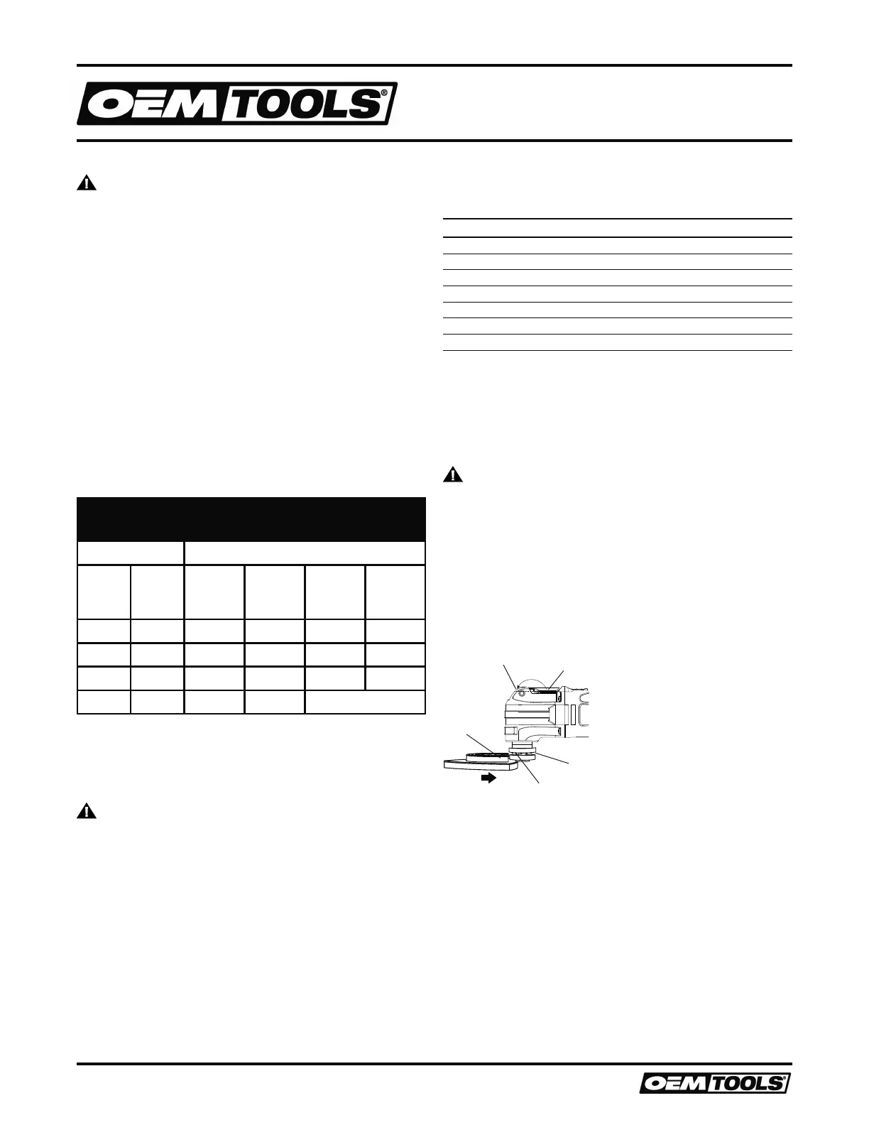
INSTALLING OPEN BACK ACCESSORIES
1. Lift the tool less accessory holder release lever (4) up and toward the
front of the tool as far as it will go (5). (Figure 1)
6
7
8
4
5
Fig. 4
1
2
Fig. 5
Fig. 3
1
2
3
4
5
6
7
8
9
10
Fig. 6
1
Fig. 7
1
Fig. 8
1
2
3
4
Fig. 9
1
2
Fig. 10
1
2
1
2
3
Fig. 11
Fig. 12
4
5
6
7
8
9
10
Figure 1
NOTE: This will open the tool less blade holder to accept the accessory.
2. Insert the accessory mount (7) into the opened accessory holder.
3. Align the accessory mounting slots and holes with the accessory
mounting teeth (8) in the accessory mount.
NOTE: The slots and holes in the accessory must be engaged with the
matching teeth on the accessory holder to allow the accessory to be
secured within the accessory holder.
4. Move the tool less accessory release lever back to its original position
(4) to clamp the accessory into the accessory holder.
NOTE: Check to make sure the accessory mounting pins are still aligned
with the slots and holes in the accessory mount.
 Loading...