OFITE, 11302 Steeplecrest Dr., Houston, TX 77065 USA / Tel: 832-320-7300 / Fax: 713-880-9886 / www.ote.com
12
13. Add approximately 320 mL of test uid to the cell. Be careful not to pour
any uid on the o-ring recess. The uid level inside the cell should be
ush with the bottom of the o-ring recess.
14. Place the cell o-ring (#170-13-3) in the o-ring groove and place the pre-
pared ceramic disk on top.
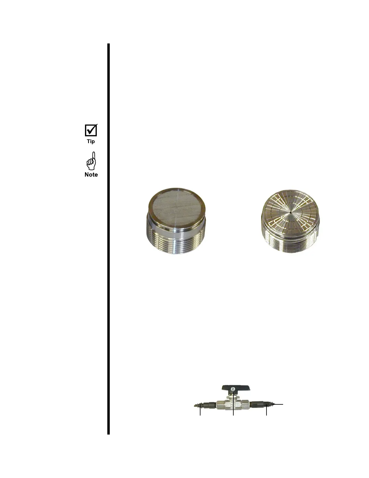
15. Find the cell cap with the scribed ow lines in the surface. Screw the cell
cap into the outlet end of the test cell. Coating the o-ring with a thin coat
of high-temperature silicone grease will help.
Use a spanner wrench or strap wrench to prevent cell body rotation while
installing the “outlet” end cap.
If you are using lter paper instead of a ceramic disk, use the provided
screened cell cap to prevent tearing. The screened cap is 2½" thicker to
account for the missing disk.
16. The space between the lter medium and the ball valve should be lled
with base uid prior to starting the test. This will ensure that the volume
of ltrate passing through the lter will displace an equal volume of lter-
ate into the receiver.
a. Close the outlet ball valve.
b. Using a syringe, inject base uid into the valve stem that connects to
the cell cap. Make sure the valve stem is completely lled.
17. Screw the outlet valve stem assembly into the cell cap. Loosen it one half
turn.
Screened Cell Cap Scribed Cell Cap
To Back Pressure
Receiver (#171-90-10)
Ball Valve
(#171-97)
To Cell Cap
(#171-90-09)
Fill With Base Fluid