PART # 1608990
STATIC BRIDGE & RETURN MODULE
INSTALLATION INSTRUCTIONS
IMPULSE G2/PULSE
INSTRUCTIONS
TOOLS REQUIRED:
Drill
Outside Access
Panel
Support
Panel
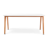
Desk
Connecting
Panel
Bridge
Back Panel
Support
"L" Bracket
Static Bridge & Return Module Installation
This sheet covers the steps to install a
static
bridge or return module with the "
FX
" no hinged access panel back
•
option to a height adjustable freestanding desk.
Begin by removing the outside access panel on the connecting end of the desk. The access panel can be
•
removed by lifting upwards and then outward as illustrated in the upper most view. Next, remove the two outer
most factory installed screws on the connecting panel of the desk, as shown in the view above. The inner most
screws will be removed at a later time.
Locate the loose support panel included with your height adjustable desk. Place it directly against the
•
connecting end of the desk, making sure the bottom edges are flush with each other, and that the back edge
will align with the face of the access panel. Secure the panel in place by fastening the supplied wood screws
from the HK-67 kit through the clearance holes and into the support panel, as shown above. A pilot hole can be
drilled prior to fastening the screws. Repeat the process for the remaining inner most screws. The access panel
can now be re-installed.
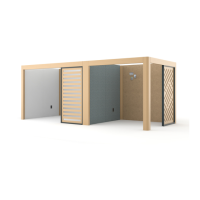
Position the bridge/return next to the desk, making sure all are aligned with each other and level. Once the
•
modules are in their correct position, fasten together by using the supplied "L" brackets and wood screws from the
HK-10 kit as shown above.
1608990
Rev:
Dwg:
1. This sheet covers the steps to install a static bridge or return module
with the “FX” no hinged access panel back option to a height adjustable
freestanding desk.
2. Begin by removing the outside access panel on the connecting end of
the desk. The access panel can be removed by lifting upwards and then
outward as illustrated in the upper most view. Next, remove the two
outer most factory installed screws on the connecting panel of the desk,
as shown in the view below. The inner most screws will be removed at a
later time.
3. Locate the loose support panel included with your height adjustable
desk. Place it directly against the connecting end of the desk, making
sure the bottom edges are flush with each other, and that the back edge
will align with the face of the access panel. Secure the panel in place
by fastening the supplied wood screws from the HK-67 kit through the
clearance holes and into the support panel, as shown below. A pilot hole
can be drilled prior to fastening the screws. Repeat the process for the
remaining inner most screws. The access panel can now be re-installed.
4. Position the bridge/return next to the desk, making sure all are aligned
with each other and level. Once the modules are in their correct position,
fasten together by using the supplied “L” brackets and wood screws from
the HK-10 kit as shown below.
TOOLS REQUIRED:
Drill
Outside Access
Panel
Support
Panel
Desk
Connecting
Panel
Bridge
Back Panel
Support
Panel
"L" Bracket
Static Bridge & Return Module Installation
This sheet covers the steps to install a
static
bridge or return module with the "
FX
" no hinged access panel back
•
option to a height adjustable freestanding desk.
Begin by removing the outside access panel on the connecting end of the desk. The access panel can be
•
removed by lifting upwards and then outward as illustrated in the upper most view. Next, remove the two outer
most factory installed screws on the connecting panel of the desk, as shown in the view above. The inner most
screws will be removed at a later time.
Locate the loose support panel included with your height adjustable desk. Place it directly against the
•
connecting end of the desk, making sure the bottom edges are flush with each other, and that the back edge
will align with the face of the access panel. Secure the panel in place by fastening the supplied wood screws
from the HK-67 kit through the clearance holes and into the support panel, as shown above. A pilot hole can be
drilled prior to fastening the screws. Repeat the process for the remaining inner most screws. The access panel
can now be re-installed.
Position the bridge/return next to the desk, making sure all are aligned with each other and level. Once the
•
modules are in their correct position, fasten together by using the supplied "L" brackets and wood screws from the
HK-10 kit as shown above.
1608990
Rev:
Dwg:
Desk Connecting Panel
Support
Panel
Bridge
Back
Panel
Support
Panel
Outside
Access
Panel
Drill
Tools Required:
“ L”
Bracket