EasyManua.ls Logo

OilGear A2 Series - User Manual

Default Icon
28 pages
Print Icon
To Next Page IconTo Next Page
Loading...
THE OILGEAR COMPANY
905 South Downing Street
Fremont, NE 68025 USA
www.oilgear.com
Issued: May 2019
PUMP SERVICE MANUAL
Bulletin 948034A
Bulletin 948034A
Figure 1. Typical Oilgear “PVG” Open Loop Pump
PURPOSE OF INSTRUCTIONS
These instructionswillsimplifythe installation,
operation, maintenance andtroubleshooting of
Oilgear type “PVG” pumps.
Become familiar withthe construction, principl
eo
f
operation and characteristicsofyour pumpto help
youattainsatisfactory performance, reduce shut-
down and increasethe pump'sservice life.Some
pumps have been modified from those described in
this bulletin and other changesmay be made
without notice.
REFERENCE MATERIAL
Fluid Recommendations........................................................................................................................... Bulletin 90000
Contamination Evaluation Guide ............................................................................................................ Bulletin 90004
Filtration Recommendations..................................................................................................................... Bulletin 90007
Piping Information .................................................................................................................................... Bulletin 90011
Installation of Vertically Mounted Axial Piston Units................................................................................. Bulletin 90014
PVG Open Loop Pumps, Sales ............................................................................................................Bulletin 47019-K
Pump Control Instructions, Series A1
“P-1NN” Single Pressure Compensator ................................................................................................ Bulletin 948675
“P-1NN/F” Single Pressure Compensator w/Load Sense ..................................................................... Bulletin 948676
“P-1NN/H” Single Pressure Compensator w/H.P. Limiter ..................................................................... Bulletin 948677
“P-1NN/G” Horsepower Limiter w/Load Sense .................................................................................... Bulletin 948678
“P-1NN/K” Single Pressure w/Load Sense, Minimum Standby ............................................................ Bulletin 948683
“P-1NN/L” Single Pressure w/HP Limiter & Load Sense, Minimum Standby ....................................... Bulletin 948684
“P-2” Dual Pressure Compensator ...................................................................................................... Bulletin 948679
“P-C & P-K” Single Pressure - Soft Start ............................................................................................. Bulletin 948680
“P-CNN/H & P-KNN/H” Single Pressure - Soft Start w/H.P. Limiter...................................................... Bulletin 948681
“P-2NN/H” Dual Pressure Compensator w/H.P. Limiter........................................................................ Bulletin 948682
“P-E” Electronic Displacement Control ................................................................................................ Bulletin 948690
“P-E/F” Electronic Displacement Control w/Load Sense ..................................................................... Bulletin 948691
OILGEAR TYPE “PVG” PUMPS
180 (SERIES A2)
SERVICE INSTRUCTIONS

Other manuals for OilGear A2 Series

Question and Answer IconNeed help?

Do you have a question about the OilGear A2 Series and is the answer not in the manual?

Summary

PURPOSE OF INSTRUCTIONS

REFERENCE MATERIAL

Lists related Oilgear bulletins for fluid, filtration, piping, and sales.

Pump Control Instructions, Series A1

Lists specific pump control types with their corresponding bulletin numbers.

SAFETY FIRST

SAFETY SYMBOLS

Defines DANGER, WARNING, CAUTION, and NOTE signal words used in the manual.

General Safety Warnings

Covers critical warnings about system pressure, leaks, and unsafe environments.

Hydraulic System Safety

Details safety for hoses, fluid handling, pipe specifications, and pressure relief.

Component Handling and PPE

Covers lifting heavy components, using correct gauges, avoiding modifications, and wearing protective gear.

PREPARATION AND INSTALLATION

MOUNTING

Provides recommendations for mounting the pump, with or without a reservoir.

PIPING AND FITTINGS

Details piping requirements, inlet velocity, and case drain line arrangement.

POWER AND DRIVE

Discusses power requirements, motor recommendations, and drive rotation/coupling.

FILTRATION AND FLUID MANAGEMENT

FLUID COOLING

Addresses the need for auxiliary cooling at high loads or pressures.

AIR BREATHER

Details the function and maintenance of the air breather.

FLUID, FILLING AND STARTING RECOMMENDATIONS

PRINCIPLE OF OPERATION

Pump Delivery Operation

Explains the pump's operation during full delivery from a specific port.

Half Delivery and Neutral Operation

Illustrates half delivery and explains the neutral state of the pump.

SPECIFICATIONS

TROUBLESHOOTING

TESTING AND ADJUSTING

DISASSEMBLY

Provides instructions and safety warnings for disassembling the pump.

DISASSEMBLY PROCEDURES

CONTROL GROUP

Describes the steps to remove the control group from the pump assembly.

VALVE PLATE GROUP

Outlines the procedure for removing the valve plate assembly.

ROTATING GROUP

DRIVE SHAFT GROUP

Explains how to remove the drive shaft and related components.

SWASHBLOCK GROUP

Covers the removal and inspection of the swashblock.

INSPECTION GUIDELINES

Guides on cleaning and inspecting pump components for wear or damage.

ROTATING GROUP (CONTINUED)

HYDRODYNAMIC BEARING

Describes the hydrodynamic bearing and its removal process.

ASSEMBLY

Hydrodynamic Bearing Installation

Details the process of pressing in a new hydrodynamic bearing using a special tool.

SWASHBLOCK GROUP ASSEMBLY

Covers the installation of the swashblock and saddle bearings.

ASSEMBLY (CONTINUED)

DRIVE SHAFT GROUP

Instructions for installing the drive shaft and bearing assembly.

VALVE PLATE GROUP ASSEMBLY

Instructions for installing the valve plate and O-rings.

PVG PUMP TORQUES

PARTS LIST

O-RING SEALS

SERVICE KITS

SPARE PARTS AVAILABILITY

Overview

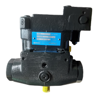
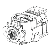
The provided document is a service manual for the Oilgear Type "PVG" 180 (Series A2) Open Loop Pump. This manual details the installation, operation, maintenance, and troubleshooting procedures for the pump.

Function Description:

The Oilgear Type "PVG" 180 (Series A2) pump is an open-loop axial piston pump designed to deliver fluid in proportion to volume and pressure used. It operates by rotating a splined cylinder containing pumping pistons. These pistons move in and out within their bores as shoes ride against an angled swashblock. As the cylinder rotates, individual piston bores are alternately connected to crescent-shaped ports in the valve plate. When connected to the suction port, pistons move outward, drawing fluid into the bore. When connected to the discharge port, pistons are forced inward, displacing fluid through the crescent to the port. The swashblock's angle determines the piston stroke length and, consequently, the pump's delivery volume. In a neutral position, the swashblock angle is zero, and its face is parallel to the cylinder face, resulting in no inward or outward piston motion and thus no fluid displacement or delivery. The pump can be driven clockwise or counterclockwise, and its rotation direction must match the drive unit.

Important Technical Specifications:

The manual provides nominal performance data for the PVG 180 pump with 150-300 SSU viscosity fluids:

  • Theoretical Maximum Displacement: 11.00 in³/rev (180.0 ml/rev)
  • Rated Continuous Pressure: 5000 psi (344.8 bar)
  • Peak Pressure: 5800 psi (400.0 bar)
  • Flow Rate at 1800 rpm rated continuous pressure and 14.7 psia (bar abs) inlet condition: 78.0 gpm (295.3 l/mi)
  • Maximum Speed: 2400 rpm
  • Power Input at rated continuous pressure & 1800 rpm: 260 hp (193.9 kW)
  • Case Pressure: Should be less than 25 psi (1.7 bar). Higher case pressures require factory consultation.
  • Nominal Dimensions (without controls):
    • Length: 15.1 inches (383.3 mm)
    • Width: 8.4 inches (213.4 mm)
    • Height: 8.9 inches (226.1 mm)
    • Weight: 197 lbs (90 kg) (with "P-1NN" Control and thru shaft valve plate)
    • Face Mounting: SAE "D" 4 bolt
  • Inlet Velocity: Must not exceed 5 fps (1.5 mps).
  • Case Pressure: Must be less than 25 psi (1.7 bar).
  • Drive Shaft Torque (by hand): 9 to 24 ft·lb (12 to 32 N•m)
  • Pump Shaft to Driver's Shaft Misalignment: Should not exceed 0.005 inches (0.13 mm) Total Indicator Readout (TIR) in any plane.
  • Piston and Shoe Inspection: All shoes must be equal within 0.002 inches (0.025 mm) at a specified dimension, and shoe faces must be free of nicks.
  • End Play: Should not exceed 0.002 inches (0.076 mm) when new or 0.006 inches (0.152 mm) when worn.

Usage Features:

  • Mounting: The pump can be mounted in any position, but the recommended position is with the drive shaft on a horizontal plane and case drain port 1 on the top side. It should be secured to a rigid mounting surface. For pumps with a reservoir, the reservoir should be on a level foundation at least six inches above the floor.
  • Piping: Refer to Oilgear Piping Information Bulletin 90011 and individual circuit diagrams. The inlet should be unrestricted with a minimum of fittings, and an inlet strainer should NOT be used. The case drain line must be separate, unrestricted, full-sized, and connected directly to the reservoir below the lowest fluid level, ensuring the case remains full of fluid (non-siphoning).
  • Drive: Direct drive coupling is recommended. The coupling should be sized and installed per the manufacturer's instructions. Do not drive the coupling onto the pump drive shaft; heating may be necessary if it's too tight.
  • Fluid and Starting: Fill the reservoir through a clean filter (beta 10 ratio of 4 or more) to the "high level" mark. Fill the pump case with hydraulic fluid by removing the case drain line. Turn the drive shaft by hand several times to ensure parts rotate freely. When starting, turn the drive unit ON and OFF several times before allowing the pump to reach full speed. The system can usually be filled by running the pump and operating the control. Fluid level in the reservoir should decrease but must not go below the "low level" mark. Bleed air from the system by loosening connections or opening petcocks at the highest point until a solid stream of fluid appears.
  • Controls: The pump is equipped with various controls, such as single pressure compensators, load sense, HP limiters, dual pressure compensators, soft start, and electronic displacement controls. Specific instructions for these controls are provided in referenced bulletins.
  • Safety: The manual emphasizes numerous safety warnings, including the importance of relieving hydraulic pressure before servicing, wearing proper protective gear, avoiding contact with hot oil, using correct hoses and fittings, and ensuring the work environment is clean and free of abrasive particles. It also warns against operating the pump in NEUTRAL for extended periods without a supercharge circuit, which can cause damage.

Maintenance Features:

  • Filtration: Maintain clean fluid using a filter in the pressure or return line. Replace filter elements when the condition indicator reaches the change area. Drain and clean the filter case, using replacement elements of the same beta 10 ratio.
  • Fluid Cooling: Auxiliary cooling may be necessary for continuous operation at rated pressure or frequent peak loads. Fluid temperature should not exceed limits specified in Fluid Recommendations Bulletin 90000.
  • Air Breather: Ensure the air breather is adequately sized and filled to the "fluid level" mark. Clean the breather screen every six months.
  • Troubleshooting: A detailed troubleshooting table is provided, listing common problems (e.g., unresponsive control, insufficient pump volume, irregular operation, loss of pressure, excessive noise, excessive heating) along with their causes and remedies.
  • Testing and Adjusting: To check for a worn piston pump, perform a leak measurement test from the case drain under pressure. Install a flow meter or direct the drain flow into a container. The pump case must remain full of fluid during the test. Run the pump on stroke against a blocked output (protected by a high-pressure relief valve) to raise system pressure to maximum. Read the flow meter or time the case drain flow to calculate the flow rate. Increased leakage indicates wear, but it only becomes critical when performance is impaired.
  • Disassembly and Assembly: The manual provides step-by-step instructions for disassembling and assembling the pump's main groups: Control Group, Valve Plate Group, Rotating Group, Drive Shaft Group, and Swashblock Group. It stresses the importance of cleanliness, using new seals and O-rings, and lubricating components during assembly. Special tools may be required for certain operations, such as pressing the hydrodynamic bearing.
  • Inspection: All parts, especially seals, O-rings, locating pins, springs, cylinder barrel, valve plate, piston/shoe assemblies, swashblock, and shaft bearings, should be thoroughly cleaned and inspected for wear, cracks, or damage. Minor defects on mating surfaces can be removed by light stoning, but extensive wear requires replacement. If one piston/shoe assembly needs replacement, all piston/shoe assemblies should be replaced.
  • Torque Specifications: A table lists tightening torques for various fasteners and plugs, including socket head cap screws (SHCS), hex head cap screws (HHCS), and SAE plugs, with their respective head types and sizes.
  • Parts List and Service Kits: Comprehensive parts lists are provided for the Housing Assembly, Drive Shaft Assembly, Rotating Group, Swashblock Assembly, Valve Plate Assembly, and Thru Drive Assembly. O-ring seal specifications (ARP 568 Size Number / Shore A Durometer for Viton or Buna and EPR) are also included. Service kits are available for various components, categorized by seal type (Viton, Buna, EPR) and shaft/coupling configurations.
  • Spare Parts Availability: Oilgear encourages stocking original factory parts and offers parts kits to minimize downtime. Field Service Technicians are available for assistance.

OilGear A2 Series Specifications

General IconGeneral
BrandOilGear
ModelA2 Series
CategoryWater Pump
LanguageEnglish

Related product manuals