Do you have a question about the OKIDATA Microline 395 and is the answer not in the manual?
Provides a general overview of the printer's capabilities and emulations.
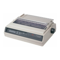
Details the printer's high-speed, dot matrix technology and standard interfaces.
Lists paper feed, printhead, interfaces, speed, symbols, fonts, and paper detection.
Details Mean Time Between Failure (MTBF), MTTR, printer life, and printhead life.
Introduces the electrical system of the printer.
Describes the Control Board's components and power distribution.
Details microprocessors, ROM, DRAM, CGROM, EEPROM, and LSIs.
Describes the printer initialization process upon power-on or reset.
Explains how serial and parallel interfaces are selected and controlled.
Explains the circuit for driving the 24 print wires and head drive duration.
Describes the circuit that controls carriage spacing via the servo motor.
Explains the circuit responsible for feeding paper line by line.
Details fault alarm, printhead overheat alarm, and cover open alarm circuits.
Explains how the printer detects the end of paper in various feed modes.
Details the switching power supply's function and voltage outputs.
Introduces the mechanical systems of the printer.
Introduces the maintenance section covering replacement, adjustment, and cleaning.
Provides essential safety and handling precautions for maintenance.
Introduces the procedures for disassembling and assembling printer components.
Details the procedure for adjusting the printhead gap.
Introduces the printer cleaning section and general precautions.
Introduces lubrication procedures, intervals, and recommended lubricants.
Lists initial checks to perform before diagnosing problems.
Provides a flowchart to guide troubleshooting based on initial symptoms.
Explains how the ALARM lamp indicates errors and the use of the Alarm Codes Table.
Provides steps on how to use the RAPs to diagnose problems.
| Type | Dot Matrix Printer |
|---|---|
| Resolution | 360 x 360 dpi |
| Number of Pins | 24 |
| Noise Level | 55 dB |
| Print Direction | Bidirectional |
| Connectivity | Parallel, Serial |
| Print Method | Impact Dot Matrix |
| Paper Width | 3" - 14.3" (76.2 mm - 363.2 mm) |