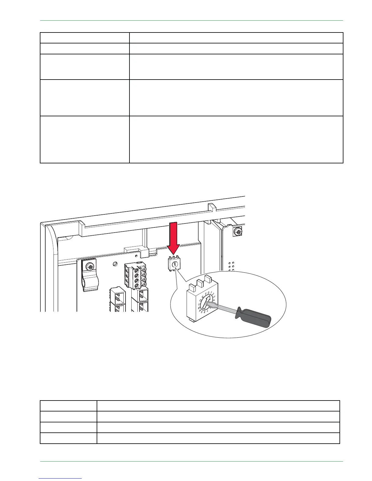
Setting the address at the heating controller
71
Base setting= 0 Switch position = 0
System with 1 boiler Switch position at boiler control = 0 (adjustment ex works)
System with 2 boiler
Switch position at boiler control boiler 1 = 0
Switch position at boiler control boiler 2 = 1
System with 3 boiler
Switch position at boiler control boiler 1 = 0
Switch position at boiler control boiler 2 = 1
Switch position at boiler control boiler 3 = 2
System with 4 boiler
Switch position at boiler control boiler 1 = 0
Switch position at boiler control boiler 2 = 1
Switch position at boiler control boiler 3 = 2
Switch position at boiler control boiler 4 = 3
1133..22..22SSeettttiinnggtthheeaaddddrreessssaatttthheehheeaattiinnggccoonnttrroolllleerr
The adress switch is inside the wall box of the heating controller.
Note:
The screwdriver for adjustment of the adress adder is enclosed to delivery of the heating controller.
At every wall box (heating controller) max. 2 heating circuits, 1 solar system (2 solar circuits), 1 DHC und 1
buffer can be connected. Alltogether max. 3 wall boxes (= 6 heating circuits, 6 solar circuits, 3 DHC and 3
buffers) are possible.
The adress adder allocates the heating circuits and DHC systems or buffers to a wall box.
Base setting Switch position= 0
Wall box A Switch position 0 = heating circuit1 + 2, Solar circuit1 + 2, DHW 1, Accumulator 1
Wall box B Switch position 1 = heating circuit 3 + 4, Solar circuit 3 +4, DHW 2, Accumulator 2
Wall box C Switch position 2 = heating circuit 5 + 6, Solar circuit 4 + 6, DHW 3, Accumulator 3
Operating Manual PELLEMATIC® PE(S)(K)(B) 10 — 56


 To Next Page