Home
Oldham
Security Sensors
ctx 300
Page 16 (Operating Mode)
Oldham ctx 300 - Operating Mode
64 pages
Manual
Save Page as PDF
To Next Page
To Next Page
To Previous Page
To Previous Page
Loading...
16
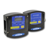
CTX 30
0
User manual
Operating mode
CTX300 with displa
y
■
Remove the 4 screws (ref
.
1).
■
Remove the cover (ref
.
2
).
Fig
ure
9
■
Completely remove the screw (ref. 4).
■
Unscrew
the
screw
a
few
turns
(ref. 3).
Fig
ure
10
■
Turn
the
display
circuit
as
shown
(ref. 5).
■
Connect
the
cable
(ref.
6)
to
the
connector
.
Refer
to
paragraph
Connections
for
th
e
various
types
of
sensors
on
page
13
.
■
Return the
display circuit to its
original
position and replace the cover.
Fig
ure
11
15
17
Table of Contents
Main Page
Default Chapter
3
Table of Contents
3
Chapter 1 | General Information
5
Symbols Used
5
User Manual
5
Important Information
6
Safety Instructions
6
Liability Limits
7
Chapter 2 | Introduction
9
General Information
9
Overview of CTX 300 with Display and Without Display
9
Composition
10
Chapter 3 | Installation and Connection
11
Determining the Best Sensor Location
11
Installing the Detectors
11
Layout
11
Drilling Diagram for Wall Mounting
12
Mechanical Installation
12
Overall Dimensions of the CTX 300
12
Ceiling Mounting with a Brace
13
Connections for the Various Types of Sensors
13
Electrical Connections
13
Wiring Specifications
13
Connection of a 2-Wire Sensor to an Oldham Control Unit
14
Connection of a 3-Wire Sensor to an Oldham Control Unit
14
Connection of 2-Wire 4-20Ma Sensor to Non-Oldham Control Unit
15
Connection of 3-Wire CTX300 Sensor to Non-OLDHAM Control Unit
15
Operating Mode
16
Chapter 4 | Powering up and Use
19
CTX 300 Circuit Board
19
CTX 300 SC Main Circuit Board
19
Powering up
19
4-20 Ma Analog Output
20
CTX 300 CO Main Circuit Board
20
Calibration
21
Chapter 5 | Maintenance
21
Recommendations
21
CTX 300 Calibration
22
Sensor Calibration Assembly
22
CTX 300 Calibration for O2
26
CTX 300 CO2 Calibration
29
Calibration Curves
30
CTX 300 CO2 Linearization Card
30
Signal CO2 -IR Transmitter Output Signal
31
Signal CO2-IR Transmitter Output Signal
32
Disposal
35
Replacing a Sensor
35
Chapter 6 | Spare Parts
37
CTX/COX 300 Toxic or Oxygen Sensors
37
CSC 300 Semiconductor Sensors
40
CTX 300 – CO2 Sensors
41
Chapter 7 | Certification
43
Chapter 8 Technical Specifications
47
Chapter 9 | Annex
51
Wiring Specification
51
Indications for Calibrating the CTX 300 SC
53
CTX 300 Overview
54
CTX 300 with Sensor Pack and Display
54
CTX 300 Semiconductor
56
CTX 300 Infrared – 1% Volume CO2
57
CTX 300 Infrared – 5% Volume CO2
58
CTX 300 Infrared – 10% Volume CO2
59
CTX 300 Infrared – 50% Volume CO2
60
Related product manuals
Oldham AirAware
28 pages