Page 22
WIRELESS H2S TRANSMITTER (WT SERIES) - USER GUIDE
11. WIRING, WT-H2S-A ONLY
1. External Alarm Device
The solid state relay outputs of the WT-H2S-A are intended to trigger the
inputs of user-supplied external alarm annunciation controllers such as
PLC's. They are unable to meet the current requirements of typical
annunciation devices, i.e. lights and sirens.
CAUTION: The WT-H2S-A cannot power external devices.
CAUTION: In hazardous locations, connect externally powered alarm
device(s) in compliance with IS Control drawing 09-0222-001.
External Alarm Device
Connect the wiring to the external device according to the manufacturer's
instructions. Verify that the external device functions properly.
Perform a bump test. See the Bump testing section.
If available, use the external device's manual test function to verify proper
function.
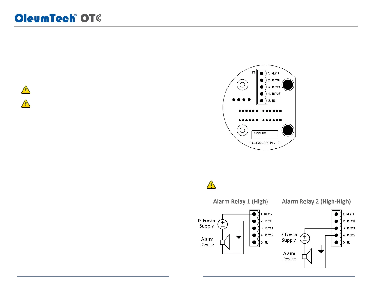
2. Alarm Relay Wiring (WT-H2S-A Only)
a. The solid state relay output wiring terminals are located inside the
junction box housing.
b. The WT-H2S-A provides 2 solid state relay outputs. Relay 1 is for Alarm
1 (high level alarm). Relay 2 is for Alarm 2 (high-high level alarm).
c. Wiring diagram shown with an Intrinsically Safe power supply and
alarm device for both solid state relay outputs.
Maximum input power rating: 28.8 Vdc / 120 mA
Refer to the IS Control Drawing for additional details.



 To Next Page