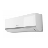
PHENIX E INVERTER
9-12 3/8” - 9,52 1/4” - 6,35 12
ENGLISH
EN - 19
2.6.3 - Execution, installation and connection of the refrigeration lines
Do not make the connections using normal hydraulic piping, which could contain
scrap residues, dirt or water, and which can damage the unit components and
jeopardise correct operation of the appliance.
Only usecopperpiping,specic forrefrigeration,whichissuppliedcleanand
sealed at the ends.
When the cuts have been made, seal the end of the roll and piece cut immediately.
Pre-insulated copper pipes can be used for refrigeration.
Onlyusepipeswithdiametersthatreectthedimensionsdescribedinthe“Technicaldata”paragraph.
Identify the route of the piping in a way to reduce the length and bends as much as possible in order to obtain
maximum system performance.
Performanceisbasedonstandardlengthandmaximumlengthallowed.
Oilcollectorsfor5-7metresmustbeinstalled(gure17).
The minimum recommended length of the pipes is 3 metres, while the length of
the pipelines covered by preload is equal to 5 metres. Beyond that length it is
necessary to add the quantity of load indicated in the table below.
To establish whether the gas load needs to be topped-up, refer to the table below.
Key(gure17)
1 Indoor unit
2 Outdoor unit
3 Oil collector
- Max. elevation (see table 17 “A”)
- Max. lengthù (see table 17)
The refrigerant should be charge from the service port on the outdoor unit’s low
pressure valve.
Piping connections must be outdoors.
a. Fasten a cable raceway to the wall (possibly with internal partitioning) of suitable size for the pipes and
electric wires to pass through.
b. Cut the sections of pipe leaving an extra 3÷4 cm on the ends.
Useawheelpipecutteronlytocutthepipes(g.18)clampingitinshortlengths
so as not to crush the pipe.
Model
Gas pipe
ø
Liquidpipe
ø
Additional
refrigerant
g/m