ISS0011R10_A_EN.doc
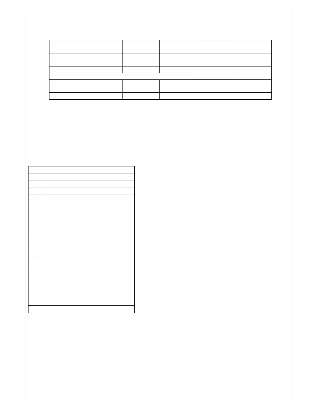
10. DISPLAY INDICATIONS
DESCRIPTION GREEN LED YELLOW LED GREEN LED RED LED
Standby ON
Machine on ON
Timer(s) on ON ON
Automatic operation ON ON
Malfunctions
“Dirty filter” malfunction ON L*
‘Probe KO’ malfunction ON L* ON L* ON L*
SELF-TEST operation ON L* ON L* ON L* ON L*
*) ON L = blinks for 1 second ON, 1 sec. OFF.
WIRING DIAGRAM
A1 Electronic power board
A2 Electronic command board
B1 Thermostat probe
F1 Compressor thermal protection
K1 Relay for compressor
K2 Relay for fan (MED)
K3 Relay for fan (MAX)
K4 Relay for fan (MIN)
M1