MONTAGGIO
I AT TEN ZIO NE
DU RAN TE IL MON TAG GIO NON E’ AM MES SO
NES SUN ESTRA NEO AI LA VO RI.
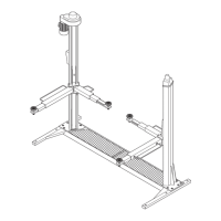
MONTAGGIO STRUTTURA MOBILE (PIATTAFORMA)
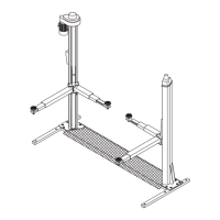
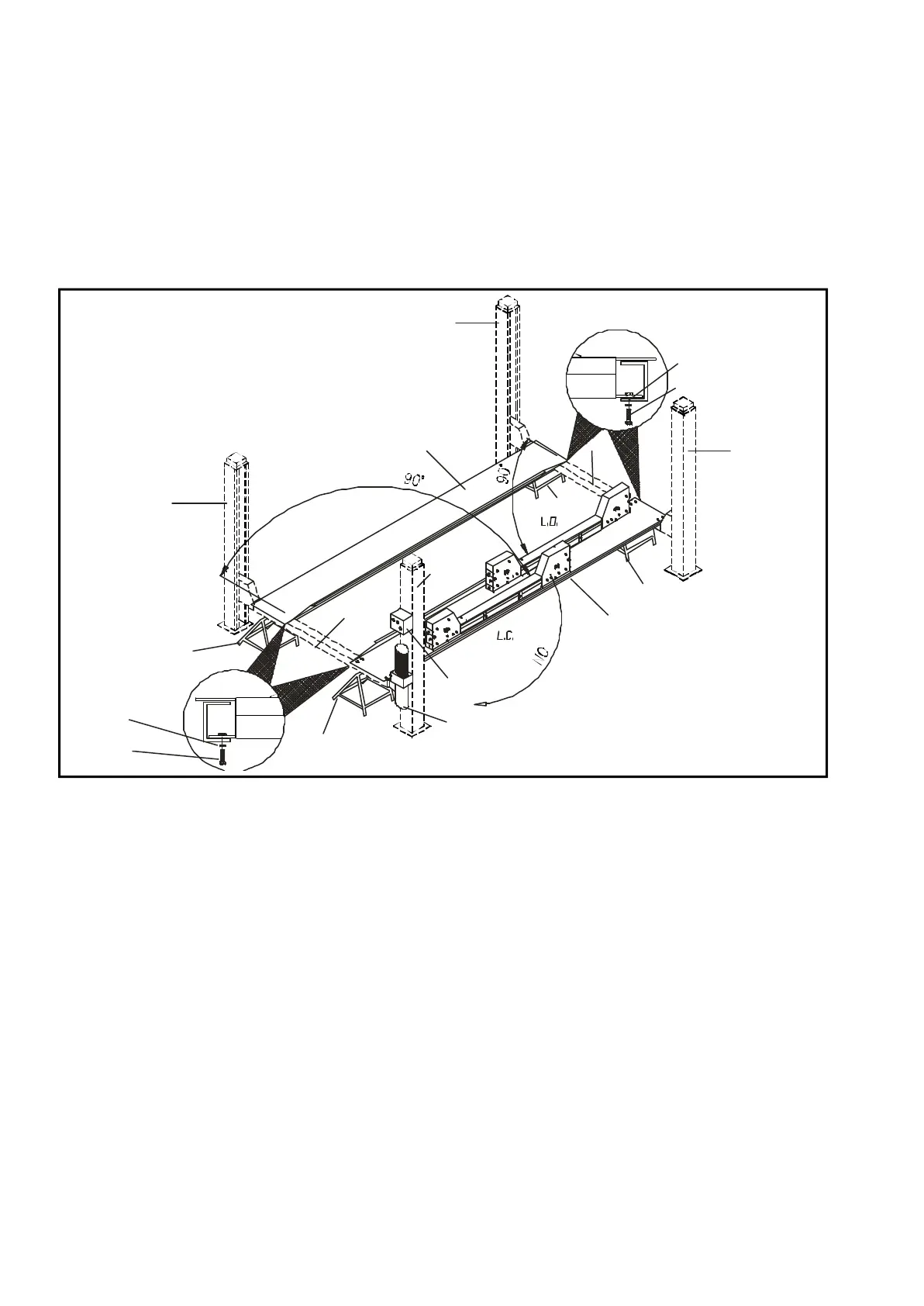
1 - Nell’a rea pre de sti na ta all’in stal la zio ne del pon te pre di spor re 4
ca val let ti di so ste gno aven ti la me de si ma al tez za, ade gua ti al peso
da so ste ne re (250kg. ca dau no ) edi spor li come in fi gu ra (A- B- CD).
Fig.39
2 - To glie re dall’imballo le co lon ne (1-2-3-4),le pe da ne (7-8),la cen
-
tra li na idra u li ca (10) e gli ac ces so ri .
3 - Pre di spor re sui 2 ca val let ti (A - D) la pe da na (7) con le due tra -
ver se (5 - 6)
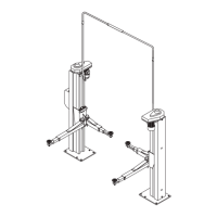
4 - Po si zio na re la tra ver sa (5) sul ca val let to (B) ed av vi tar la sul la
pe da na (7) me dian te le viti (15) M12 x 25 e le ro set te den ta te (16)
Ø12 x 20.
Du ran te que sta fase é im por tan te ve ri fi ca re che le funi sia no in po
-
si zio ne cor ret ta (vedi part. “C” in Fig.40) .
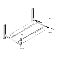
5 - Po si zio na re sul le tra ver se (pos.5-6, Fig.39) la pe da na (8).
6 - Ve ri fi ca re la squa dra tu ra e le dia go na li dell’assieme tra ver
-
se-pe da ne; quin di ser ra re a fon do le viti (15) di fis sag gio delle pe
-
da ne (7-8).
ASSEMBLY
I WAR NING
UNAUT HO RI SED PER SONS MUST NOT BE AD -
MIT TED DU RING AS SEM BLY OPE RA TIONS.
ASSEMBLY OF MOVABLE STRUCTURE (PLATFORM)
1 - Pla ce 4 trestles of the same height and sui ta bly sturdy to hold
250 kg each, in the area whe re you in tend to in stall the lift. Po si tion
the trestles as shown in the fi gu re (A- B- C-D).
Fig.39
2 - Re mo ve the posts from the pac king (1-2-3-4), to get her with the
plat forms (7-8), the hydra u lic po wer unit (10) and ac ces so ries.
3 - Pla ce the plat form (7) on two tre stles (A - D) to get her with the
two cross-pie ces (5 - 6)
4 - Pla ce the cross-pie ce (5) on tre stle (B) and se cu re it to the plat -
form (7) using M12 x 25 screws (15) and 12 x 20 to ot hed wa shers
(16).
Du ring the se ope ra tions check that the ste el ca bles are cor rectly
po si tio ned (see view “C” in fig.40).
5 - Pla ce the plat form (8) on the cross-pie ces (pos.5-6, fig.39).
6 - Check squa ring and the dia go nals of the cross-pie ce - plat form
as sembly; then, fully tig hten the screws (15) se cu ring the plat forms
(7-8).
24
15
16 10
9
A
C
B
D
8
7
6
5
3
4
1
2
15
16
 Loading...