Prima di eseguire alcuna manovra controllare:
1) il li vel lo dell’o lio, even tual men
-
te rab boc ca re con olio mi ne ra le
per im pian ti oleo di na mi ci
ISO 32 - H-LP DIN 51525
2) il sen so di ro ta zio ne del mo to -
re, pre men do per un istan te il pul
-
san te di sa li ta
“AT TEN ZIO NE” una pro lun ga ta
ro ta zio ne in sen so con tra rio può
crea re gra vi dan ni alla pom pa.
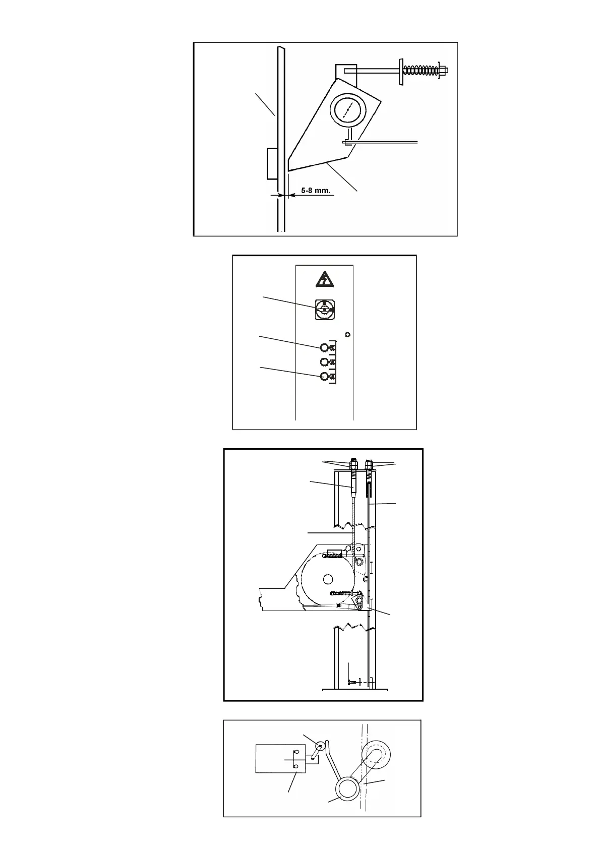
3) la re go la re aper tu ra dei mar tel -
let ti.Te nen do pre mu to il pul san te
di di sce sa ve ri fi ca re che la di -
stan za tra la si cu rez za e l’a sta sia
di 5-8 mm fig.49 una di stan za in
-
fe rio re po treb be cau sa re l’ag gan -
cio ac ci den ta le del la si cu rez za,
una di stan za su pe rio re im pe di reb -
be la per fet ta chiu su ra
dell’e let tro ma gne te ori gi nan do ru
-
mo ro se vi bra zio ni.
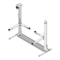
PREREGISTRAZIONI FUNI
Chiu de re il qua dro, por ta re l’interruttore
(QS) in pos. 1e far sa li re il sol le va to re fino a
li be ra re i ca val let ti (A-B-C-D), ri por ta re
l’interruttore in pos.0 quin di to glier li.
Por ta re l’interruttore ge ne ra le (QS in Fig.50)
in po si zio ne 1, pre me re il pul san te di di sce
-
sa (SB2) e ve ri fi ca re che il sol le va to re scen -
da. Se cio’ non av ve nis se ve ri fi ca re la re go -
la zio ne dei 4 sen so ri funi (pos.17, Fig.45) e,
se ne ces sa rio, re go lar li agen do sul la vite
del la leva di scat to del mi cro in ter rut to re
(pos.36, Fig.50).
Fig.50 Pan nel lo di con trol lo
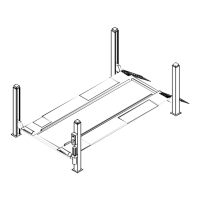
Po si zio na re il sol le va to re in modo che i 4
mar tel let ti (32), mo stra ti in Fig.51, sia no
al log gia ti den tro le aso le del le aste di si -
cu rez za (12). Agen do sui dadi (20) dei ter -
mi na li (19) del le funi (33) ese gui re le re gi
-
stra zio ni del le pe da ne (7 e 8) in modo da
ot te ne re la pla na ri tà di tut ta la par te mo bi
-
le.
Al len ta re le viti in fe rio ri (34) di fis sag gio
del le aste di si cu rez za (12) e agen do sui
dadi su pe rio ri (35) del le stes se, re go lar le
in modo da ave re un’e gua le di stan za tra i
mar tel let ti (32) e le aso le del le aste di si -
cu rez za (12) sul le 4 co lon ne (1- 2- 3-4).
Ser ra re a fon do le viti in fe rio ri (34) e bloc
-
ca re la par te su pe rio re con con tro da do
(35).
Fig.51 Pre re gi stra zio ne funi
Fig.52
Before making any manoeuvres:
1) Check the fluid le vel, and fill
if ne ces sa ry using mi ne ral oil
for hydrau lic sy stem
ISO 32 - H-LP DIN 51525
2) Check the ro ta tion di rec tion
of the mo tor by pushing the lif
-
ting push but ton mo men ta rily
WAR NING: pro lon ged ro ta tion
in the wrong di rec tion can se -
riously da ma ge the pump.
3) adjust the ope ning of the
wed ges. Kee ping the de scent
but ton pres sed, check the dis
tan ce betwe en the sa fe ty de vi
-
ce and the rod is 5-8 mm. A les
-
ser spa ce could cau se the sa fe -
ty de vi ce hoo king, whi le a grea -
ter spa ce could pre vent a per -
fect elec tro ma gnet clo su re with
con se quent noisy vi bra tion.
CABLE PRE-ADJUSTMENT
Clo se the pa nel, put the switch (QS) in pos.
1 and make the lift rise un til cle a ring the
wed ges (A-B-C-D); then put the switch in
po si tion 0 and clo se them aga in. Put the
main switch (QS in fig. 49) in po si tion 1,
press the lo we ring but ton (SB2) and check
if the lift lo wers. If this do esn’t hap pen,
check the ad ju stment of the four ca ble sen -
sors (pos. 17, fig. 45) and, if ne ces sary, ad -
juststthem by ac ting on the screw of the mi -
cro switch re le a se le ver (pos. 36, fig. 50).
Fig- 50 Con trol pa nel
Po si tion the lift so that the four wed ges
(32) in fig.51 are firm ly sea ted in the slots
on the sa fe ty rods (12). Adjust the nuts
(20) on the ter mi nal blocks (19) of the lift
cables (33) to le vel the plat forms (7 and
8) so that the en ti re sur fa ce of the mo
-
vab le sec tion of the lift is per fectly le vel.
Loo sen the lower screws (34) se cu ring
the sa fe ty rods (12) and, by tur ning the
up per nuts (35) of the rods, adjust so that
the di stan ce betwe en the wed ges (32)
and the slots in the sa fe ty rods (12) is
iden ti cal on all four posts (1- 2- 3-4). Tigh
-
ten the lower screws (34) ful ly and se cu re
the up per part with the lock nut (35).
Fig.51 Pre- adjustment of lift cables
29
QS
SB2
SB1
Fune
Rope
Sen so re
Sen sor
Mi cro in ter rut to re
Mi croswitch
36
Mar tel let to
Wed ge
Asta di si cu rez za
Sa fe ty rod
Fig.49
20
19
34
32
12
35
33
 Loading...