CAP.1. DESCRIZIONE DELLA
MACCHINA
I pon ti sol le va to ri a 4 co lon ne sono fis si, cioè an co ra ti al suo lo;
sono pro get ta ti e co strui ti per il sol le va men to e lo sta zio na men to in
quo ta di au to vei co li e fur go ni.
Sono com po sti prin ci pal men te da una par te fis sa, an co ra ta al ter
-
re no (co lon ne) e da una par te mo bi le (tra ver se e pe da ne di so ste -
gno e sol le va men to).
Il fun zio na men to è di tipo elet tro i drau li co.
Que sti sol le va to ri sono com po sti, fon da men tal men te da quat tro
par ti:
- grup po strut tu ra fis sa;
- grup po strut tu ra mo bi le;
- grup po di sol le va men to;
- si cu rez ze.
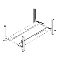
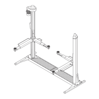
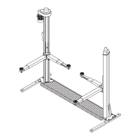
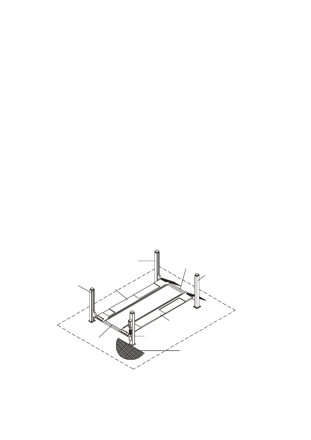
In fi gu ra 3 sono in di ca te le va rie par ti che com pon go no il sol le va to -
re e le zone di la vo ro at tor no al sol le va to re stes so.
Lato ope ra to re: è il lato an te rio re del sol le va to re, quel lo che com
-
pren de an che la zona ri ser va ta all’o pe ra to re in cui si ac ce de al
qua dro co man di ed è op po sta al lato di in gres so del sol le va to re.
Lato po ste rio re: è il lato op po sto a quel lo ope ra to re in cui si tro va -
no le ram pe di ac ces so al sol le va to re.
Lati de stro e si ni stro: sono sta bi li ti ri spet to all’o pe ra to re ri vol to ver
-
so il sol le va to re.
Zona di si cu rez za: è la zona di si cu rez za in cui non si deve mai so -
sta re quan do il sol le va to re è in fun zio ne; spie ga zio ni mag gior men -
te det ta glia te le tro ve re te nel ca pi to lo 3 “Si cu rez ze”.
La nu me ra zio ne in fi gu ra 3 si ri fe ri sce a:
1 co lon na lato co man do (si in ten de per
con ven zio ne in ter na come an te rio re de stra)
2 co lon na an te rio re si ni stra
3 co lon na po ste rio re si ni stra
4 co lon na po ste rio re de stra
5 tra ver sa lato co man do (tra ver sa an te rio re)
6 tra ver sa tra ver sa po ste rio re
7 pe da na de stra, fis sa
8 pe da na si ni stra, mo bi le
Fi gu ra 3
Fi gu re 3
CHAPTER 1. DESCRIPTION
OF THE MACHINE
Four- post lifts are fixed in stal la tions, i.e. an cho red to the flo or; the
units are de si gned and built for lif ting cars and vans and hol ding
them in an ele va ted po si tion.
The units are es sen ti al ly made up of a fixed part that is an cho red
to the flo or (posts) and a mo ving part (cross- pi e ces and plat forms).
The ope ra tion is elec tro- hydrau lic
The re are four ba sic parts of the lifts:
- fixed struc tu re as sem bly;
- mo vab le struc tu re as sem bly;
- lif ting as sem bly;
- sa fe ty de vi ces.
Fi gu re 3 shows the va rious parts of the lift and the ope ra ting zo nes
in the sur roun ding area.
Ope ra tor side: this is the front of the lift, in clu ding the area re ser
-
ved for the ope ra tor with the con trol pa nel. The ope ra tor side is op
-
po si te the vehic le ac cess side.
Rear side: it is the side op po sed the ope ra tor’s one, with the lift ac -
cess ramps.
Right and left si des: the right and left is con si de red from the ope ra
-
tor’s standpoint when facing the lift.
Sa fe ty zone: an area that must be kept clear of per sons when the
lift is in use; re fer to “Sa fe ty de vi ces” chap ter 3 for de tails.
Key to fi gu re 3:
1 con trol side post (con ven tio nal ly the front right- hand post)
2 front left post
3 rear left post
4 rear right post
5 con trol side cross- pi e ce (front cross- pi e ce)
6 rear cross- pi e ce
7 right fixed plat form
8 left mo ving plat form
6
1
5
7
8
4
3
6
2
Zona ope ra to re
Be die nungszo ne
 Loading...